UNITED STATES DISTRICT COURT
FOR THE EASTERN DISTRICT OF TEXAS
TYLER DIVISION
U.S. ETHERNET INNOVATIONS, § LLC, §
§ Plaintiff, §
§
v. § Civil Action No. 6:12-cv-00235-MHS-JDL
§ (lead case) § JURY TRIAL REQUESTED RICOH AMERICAS CORPORATION §
Defendant. § v. §
§ § Civil Action No. 6:11-cv-491-MHS-JDL § § JURY TRIAL REQUESTED
TEXAS INSTRUMENTS §
INCORPORATED, et al., § Defendants. §
MEMORANDUM OPINION AND ORDER
This claim construction opinion construes the disputed claim terms in U.S. Patent Nos. 5,299,313 (“the „313 patent”), 5,307,459 (“the „459 patent”) 5,434,872 (“the „872 patent”), 5,732,094 (“the „094 patent”) and 5,503,874 (“the „874 patent”) (collectively “patents-in-suit”). On April 4, 2013, the Court held a Markman hearing on the disputed terms of the patents-in-suit for both the 6:11-cv-491 civil action (“TI action”), and the 6:12-cv-235 civil action (“Ricoh consolidated action”), which represents the lead case in a consolidated action. In the TI action, Plaintiff U.S. Ethernet Innovations, LLC (“USEI”) alleges Defendant Texas Instruments Incorporated (“TI”) infringes certain claims of the „094 Patent, the „872 Patent, the „313 Patent, and the „874 patent. In the Ricoh consolidated action, USEI alleges the following: Ricoh2 Americas Corporation (“Ricoh”) infringes certain claims of the „094 Patent, the „872 Patent, the „313 Patent, and the „874 Patent; Xerox Corporation (“Xerox”) infringes certain claims of the „094 Patent, the „872 Patent, the „459 Patent, the „874 Patent, and the „313 Patent; Freescale Semiconductor, Inc.(“Freescale”) infringes certain claims of the „094 Patent, the „872 Patent, the „313 Patent, and the „874 Patent; Epson America, Inc. (“Epson”) infringes certain claims of the „094 Patent, the „872 Patent, the „874 Patent, and the „313 Patent; Samsung Electronics Co., Ltd., Samsung Electronics America, Inc., Samsung TeleCommunications America, LLC, and Samsung Austin Semiconductor, LLC (collectively “Samsung”) infringe certain claims of the „094 Patent, the „872 Patent, the „874 Patent, and the „313 Patent; Oki Data Americas Inc. (“Oki Data”) infringes certain claims of the „094 Patent, the „872 Patent, the „874 Patent, and the „313 Patent; and STMicroelectronics N.V. and STMicroelectronics, Inc. (“STM”) infringe „094 Patent, the „872 Patent, the „459 Patent, the „874 Patent, and the „313 Patent.1 For the reasons stated herein, the Court adopts the constructions set forth below.
CLAIM CONSTRUCTION PRINCIPLES
“It is a „bedrock principle‟ of patent law that „the claims of a patent define the invention to which the patentee is entitled the right to exclude.‟” Phillips v. AWH Corp., 415 F.3d 1303, 1312 (Fed. Cir. 2005) (quoting Innova/Pure Water, Inc. v. Safari Water Filtration Sys., Inc., 381 F.3d 1111, 1115 (Fed. Cir. 2004)). The Court examines a patent‟s intrinsic evidence to define the patented invention‟s scope. Id. at 1313–14; Bell Atl. Network Servs., Inc. v. Covad Commc’ns Group, Inc., 262 F.3d 1258, 1267 (Fed. Cir. 2001). Intrinsic evidence includes the claims, the rest of the specification and the prosecution history. Phillips, 415 F.3d at 1312–13; Bell Atl. Network Servs., 262 F.3d at 1267. The Court gives claim terms their ordinary and3 customary meaning as understood by one of ordinary skill in the art at the time of the invention. Phillips, 415 F.3d at 1312–13; Alloc, Inc. v. Int’l Trade Comm’n, 342 F.3d 1361, 1368 (Fed. Cir. 2003). Claim language guides the Court‟s construction of claim terms. Phillips, 415 F.3d at 1314. “[T]he context in which a term is used in the asserted claim can be highly instructive.” Id. Other claims, asserted and unasserted, can provide additional instruction because “terms are normally used consistently throughout the patent.” Id. Differences among claims, such as additional limitations in dependent claims, can provide further guidance. Id. “[C]laims „must be read in view of the specification, of which they are a part.‟” Id. (quoting Markman v. Westview Instruments, Inc., 52 F.3d 967, 979 (Fed. Cir. 1995)). “[T]he specification „is always highly relevant to the claim construction analysis. Usually, it is dispositive; it is the single best guide to the meaning of a disputed term.‟” Id. (quoting Vitronics Corp.v. Conceptronic, Inc., 90 F.3d 1576, 1582 (Fed. Cir. 1996)); Teleflex. Inc. v.Ficosa N. Am. Corp., 299 F.3d 1313, 1325 (Fed. Cir. 2002). In the specification, a patentee may define his own terms, give a claim term a different meaning that it would otherwise possess, or disclaim or disavow some claim scope. Phillips, 415 F.3d at 1316. Although the Court generally presumes terms possess their ordinary meaning, this presumption can be overcome by statements of clear disclaimer. See SciMed Life Sys., Inc. v. Advanced Cardiovascular Sys., Inc., 242 F.3d 1337, 1343-44 (Fed. Cir. 2001). This presumption does not arise when the patentee acts as his own lexicographer. See Irdeto Access, Inc. v. EchoStar Satellite Corp., 383 F.3d 1295, 1301 (Fed. Cir. 2004). The specification may also resolve ambiguous claim terms “where the ordinary and accustomed meaning of the words used in the claims lack sufficient clarity to permit the scope of4 the claim to be ascertained from the words alone.” Teleflex, Inc., 299 F.3d at 1325. For example, “[a] claim interpretation that excludes a preferred embodiment from the scope of the claim „is rarely, if ever, correct.‟” Globetrotter Software, Inc. v. Elam Computer Group Inc., 362 F.3d 1367, 1381 (Fed. Cir. 2004) (quoting Vitronics Corp., 90 F.3d at 1583). But, “[a]lthough the specification may aid the court in interpreting the meaning of disputed language in the claims, particular embodiments and examples appearing in the specification will not generally be read into the claims.” Constant v. Advanced Micro-Devices, Inc., 848 F.2d 1560, 1571 (Fed. Cir. 1988); see also Phillips, 415 F.3d at 1323. The prosecution history is another tool to supply the proper context for claim construction because a patentee may define a term during prosecution of the patent. Home Diagnostics Inc. v. LifeScan, Inc., 381 F.3d 1352, 1356 (Fed. Cir. 2004) (“As in the case of the specification, a patent applicant may define a term in prosecuting a patent”). The well-established doctrine of prosecution disclaimer “preclud[es] patentees from recapturing through claim interpretation specific meanings disclaimed during prosecution.” Omega Eng’g Inc. v. Raytek Corp., 334 F.3d 1314, 1323 (Fed. Cir. 2003). The prosecution history must show that the patentee clearly and unambiguously disclaimed or disavowed the proposed interpretation during prosecution to obtain claim allowance. Middleton Inc. v. 3M Co., 311 F.3d 1384, 1388 (Fed. Cir. 2002); see also Springs Window, 323 F.3d at 994 (“The disclaimer . . . must be effected with „reasonable clarity and deliberateness.‟”) (citations omitted). “Indeed, by distinguishing the claimed invention over the prior art, an applicant is indicating what the claims do not cover.” Spectrum Int’l v. Sterilite Corp., 164 F.3d 1372, 1378–79 (Fed. Cir. 1988) (quotation omitted). “As a basic principle of claim interpretation, prosecution disclaimer promotes the public notice5 function of the intrinsic evidence and protects the public‟s reliance on definitive statements made during prosecution.” Omega Eng’g, Inc., 334 F.3d at 1324. Although, “less significant than the intrinsic record in determining the legally operative meaning of claim language,” the Court may rely on extrinsic evidence to “shed useful light on the relevant art.” Phillips, 415 F.3d at 1317 (quotation omitted). Technical dictionaries and treatises may help the Court understand the underlying technology and the manner in which one skilled in the art might use claim terms, but such sources may also provide overly broad definitions or may not be indicative of how terms are used in the patent. Id. at 1318. Similarly, expert testimony may aid the Court in determining the particular meaning of a term in the pertinent field, but “conclusory, unsupported assertions by experts as to the definition of a claim term are not useful.” Id. Generally, extrinsic evidence is “less reliable than the patent and its prosecution history in determining how to read claim terms.” Id.
The patent in suit may contain means-plus-function limitations that require construction. Where a claim limitation is expressed in means-plus-function language and does not recite definite structure in support of its function, the limitation is subject to 35 U.S.C. § 112 ¶ 6. Braun Med., Inc. v. Abbott Labs., 124 F.3d 1419, 1424 (Fed. Cir. 1997). In relevant part, § 112 mandates that “such a claim limitation be construed to cover the corresponding structure . . . described in the specification and equivalents thereof.” Id. (citing 35 U.S.C. § 112 ¶ 6. ). Accordingly, when faced with means-plus-function limitations, courts “must turn to the written description of the patent to find the structure that corresponds to the means recited in the [limitations].” Id. Construing a means-plus-function limitation involves two inquiries. The first step requires “a determination of the function of the means-plus-function limitation.” Medtronic, Inc.6 v. Advanced Cardiovascular Sys., Inc., 248 F.3d 1303, 1311 (Fed. Cir. 2001). Once a court has determined the limitation‟s function, “the next step is to determine the corresponding structure disclosed in the specification and equivalents thereof.” Medtronic, 248 F.3d at 1311. A structure is corresponding “only if the specification or prosecution history clearly links or associates that structure to the function recited in the claim.” Id. Moreover, the focus of the corresponding structure inquiry is not merely whether a structure is capable of performing the recited function, but rather whether the corresponding structure is “clearly linked or associated with the [recited] function.” Id.
DISCUSSION
I. The „313 Patent
The „313 patent discloses a network interface adapter having a host interface logic that emulates memory mapped registers in the host address space. ABSTRACT „313 patent. Figure 3 depicts a block diagram of data flow:

„313 patent Fig. 3.
7There is only one term in dispute in the „313 patent, and that term is found in claim 13,
set forth below: 13. An apparatus for controlling communication be-
tween a host system and a network transceiver coupled with a network, wherein the host system includes a host address space, comprising:
a buffer memory outside of the host address space,
including a transmit buffer and a receive buffer; host interface means, sharing host address space including a prespecified block of host addresses of limited size defining a first area and a second area, and coupled with the buffer memory, for mapping data addressed to the first area into the transmit buffer, mapping data in the receive buffer into the second area, and uploading data from the receive buffer to the host; and
network interface means, coupled with the network transceiver and the buffer memory, for transferring data from the transmit buffer to the network transceiver and mapping data into the receive buffer from the network transceiver.
„313 patent at 29:57–68, 30:1–8.
A. Disputed Term
| Claim Language | Plaintiff‟s Proposal | Defendants‟ Proposal | Court‟s Construction |
| “host interface means, sharing host address space including a prespecified block of host addresses of limited size defining a first area and a second area, and coupled with the buffer memory, for mapping data addressed to the first area into the transmit buffer, mapping data in the receive buffer into the second area, and uploading data from the receive buffer to the host” | |||
| „313: 13 | Function: (1) mapping data addressed to the first area into the transmit data buffer; (2) mapping data in the receive buffer into the second area; and (3) uploading data from the receive buffer to the host. | Function: (1) mapping data addressed to the first area into the transmit data buffer; (2) mapping data in the receive buffer into the second area; and (3) uploading data from the receive buffer to the host. | Function: (1) mapping data addressed to the first area into the transmit data buffer; (2) mapping data in the receive buffer into the second area; and (3) uploading data from the receive buffer to the host. |
| The following structures, acts, or materials, and their equivalents, correspond to the recited function: 1. XMIT AREA (See, e.g., Col. 10:46- 54; Col. 16:27-32; Fig. 3, 107; Fig. 9, (DD); Fig. 10A-E (DD)); and equivalents thereto. 2. XFER AREA (See, e.g., Col. 25:34- 41; Col. 15:8-18; Fig. 3, 108, Fig. 4 (XFER AREA); Fig. 11 (XFER REGS)); and equivalents thereto. 3. upload DMA logic (See, e.g., Fig. 2, 57; Fig. 3, 108; Fig. 11, 300; Col. 2:47-51; Col. 6:13- 18; Col. 8:65-9:12; Col. 9:60-10:2; Col. 23:14-19); and equivalents thereto. | Structure: No disclosure of a single structure capable of performing all three functions, and nothing in the intrinsic evidence that would lead a person of ordinary skill in the art to group these individual components into a single component. | Structure: 1. XMIT AREA (See, e.g., Col. 10:46-54; Col. 16:27-32; Fig. 3, 107; Fig. 9, (DD); Fig. 10A-E (DD)); and equivalents thereto. 2. XFER AREA (See, e.g., Col. 25:34-41; Col. 15:8-18; Fig. 3, 108, Fig. 4 (XFER AREA); Fig. 11 (XFER REGS)); and equivalents thereto. 3. upload DMA logic (See, e.g., Fig. 2, 57; Fig. 3, 108; Fig. 11, 300; Col. 2:47-51; Col. 6:13-18; Col. 8:65- 9:12; Col. 9:60-10:2; Col. 23:14-19); and equivalents thereto. |
8Defendants maintain the above limitation is indefinite, but in the alternative agree with USEI‟s construction of the term if the Court does not find the limitation indefinite. DEFS‟ BR. at 30 (Doc. No. 170). For the reasons set forth in the Court‟s Report and Recommendation, the Court finds the term is not indefinite. Accordingly, the Court adopts the parties‟ agreed construction set forth herein.
9II. The „459 Patent
The „459 patent discloses a network adapter capable of providing an early interrupt signal to a host processor before transfer of a data frame to the network is completed. ABSTRACT „459 patent. Figure 2 sets out a functional block diagram of the adapter:

„459 patent Fig. 2. There is only one term in dispute in the „459 patent, and that term is found in claim 1, set forth below:
1.An apparatus for transferring a data frame between
a network transceiver, coupled with a network, and a host system which includes a host processor and host memory, the apparatus generating an indication signal to the host processor responsive to the transfer of the data frame, with the host processor responding to the indication signal after a period of time, comprising:
a buffer memory for storing the data frame; network interface logic for transferring the data
frame between the network transceiver and the
10buffer memory;
host interface logic for transferring the data frame
between the host system and the buffer memory;
threshold logic for allowing the period of time for the
host processor to respond to the indication signal to occur during the transferring of the data frame, wherein the threshold logic includes, a counter, coupled to the buffer memory, for
counting the amount of data transferred to or from the buffer memory;
an alterable storage location containing a threshold
value; and
means for comparing the counter to the threshold
value in the alterable storage location and generating an indication signal to the host processor responsive to a comparison of the counter and the alterable storage location.
„459 patent 42:42–68.
A. Disputed Term
| Claim Language | Plaintiff‟s Proposal | Defendants‟ Proposal | Court‟s Construction |
| “means for comparing the counter to the threshold value in the alterable storage location and generating an indication signal to the host processor responsive to a comparison of the counter and the alterable storage location” | |||
| „459: 1 | Function: (1) comparing the value generated by the counter to the threshold value in the alterable storage location; and (2) generating an indication signal to the host processor responsive to a comparison of the value generated by the counter and the value in the alterable storage location. The following structures, acts, or | Function: (1) comparing the value generated by the counter to the threshold value in the alterable storage location; and (2) generating an indication signal to the host processor responsive to a comparison of the value generated by the counter and the value in the alterable storage location. Structure: Indefinite because 1) one of ordinary | Function: (1) comparing the value generated by the counter to the threshold value in the alterable storage location; and (2) generating an indication signal to the host processor responsive to a comparison of the value generated by the counter and the value in the alterable storage location. Structure: comparator 224 (Fig. 14) |
| materials, and their equivalents, correspond to the recited function: 1. comparator (See, e.g., Fig. 14, 213; Col. 32:23-30; Fig. 14, 224; Col. 32:44- 50; Fig. 21, 318; Col. 36:6-16; Fig. 23, 341; Col. 37:58-59; Fig. 24, 511; Fig. 26, 511; Col. 38:42-50; Fig. 31, 615; Col. 40:41- 53); and equivalents thereto. 2. control block (See, e.g., Fig. 4, 60; Col. 9:13-23; Fig. 14, 210; Col. 31:41-49; Fig. 14, 225; Col. 32:31-36; Fig. 4; Col. 34:33-38; Fig. 24, 512; Fig. 27, 512; Col. 38:51-55; Fig. 33, 625; Col. 41:1- 18); and equivalents thereto. | skill in the art cannot discern a single structure performing both “comparing the counter to the threshold value” and “generating an indication signal to the host processor,” as required by claim 1, and 2) because the “comparing” structures are purely functional blocks, lacking structure by which equivalents can be discerned to determine claim scope. Alternatively, in the event that this term is not found indefinite, and without conceding that the specification contains sufficient structure: 1. Corresponding structure for “comparing the counter to the threshold value” is comparator 224, as illustrated in FIG.14. 2. Corresponding structure for “generating an indication signal to the host processor” is the “Early Rcv Control 225” in FIG. 14 (having the features of Fig. 18) combined with the host bus interface 51 as illustrated in FIG. 4 and the host bus. | control logic 225 (Fig. 14) |
12Defendants contend this limitation is indefinite, and in the alternative, Defendants agree with USEI‟s proposed function, but disagree as to the disclosed structures that perform that function. DEFS.‟ BR. at 26. For the reasons set forth in the Court‟s Report and Recommendation, the Court finds the term is not indefinite. Accordingly, the agreed function is: “(1) comparing the value generated by the counter to the threshold value in the alterable storage location; and (2) generating an indication signal to the host processor responsive to a comparison of the value generated by the counter and the value in the alterable storage location.” As to the corresponding structure for the first recited function of “comparing,” Defendants argue that the comparators identified by USEI are purely functional and therefore indefinite, but in the alternative, offer comparator 224 as the corresponding structure if the term is not found indefinite. DEFS.‟ MTN. FOR SJ, at 6–7 (Doc. No. 169); DEFS.‟ BR. at 26–27. While USEI offers a number of examples from the specification where a comparator is performing a “comparing” function, it specifically points to comparator 224 of Figure 14 as a corresponding structure for the “comparing” function of the recited claim term. PL.‟S BR. at 20 (Doc. No. 158). Thus, it appears the parties are in agreement that comparator 224 is a corresponding structure for the “comparing” function. PL.‟S BR. at 20; DEFS.‟ BR. at 26–27. Accordingly, and for the reasons further discussed in its Report and Recommendation, the Court finds comparator 224 of Figure 14 (below) to be the corresponding structure required to perform the recited function of “comparing.”
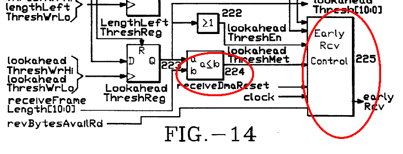
13The parties disagree as to corresponding structure for the second function of “generating an indication signal.” USEI argues the corresponding structure is control block 225 in Figure 14. PL.‟S BR. at 22. Defendants argue that control block 225 of Figure 14, along with host bus 51 of Figure 4, performs the generating function. DEFS.‟ BR. at 28. Particularly, Defendants argue that the host bus is necessary to allow for the indication signal to have a path to the host processor as recited in claim 1 of the „459 patent. Id. Accordingly, the only claim scope dispute for the Court to resolve is whether the host bus 51 of Figure 4 is a corresponding structure necessary to carry out the generating function of claim 1. The second function recited in claim 1 requires “generating an indication signal to the host processor responsive to a comparison of the value generated by the counter and the value in the alterable storage location.” „459 patent at 42:65–68. This function calls only for the generation of the signal to the host processor, a function that is readily understood by one of ordinary skill in the art to be performed by a control block, as disclosed in Figure 14. See Fig. 14; „459 patent at 32:31–32 (“CONTROL block 225 asserts EARLY RCV based on its inputs…”). While Defendants wish to include the additional structure, host bus interface 51, as a corresponding structure, that structure is not required by the recited “generating” function, as claim 1 does not recite “generating an indication signal and applying it to the host processor.” Because claim 1 does not require the signal be applied to the host processer, a function the host bus interface 51 carries out, that structure is unnecessary to perform the recited function. Here, the control block 225 of Figure 14 completes the entire “generating” function. Accordingly, the Court finds the corresponding structure for the disputed second function to be control block 225 of Figure 14.
14III. The „872 and „094 Patents
The „872 and „094 patents are related and share a common specification. The patents are directed to transmission of data in a network interface wherein frames of data formed by a host computer, according to a network protocol, are transferred into a transmit buffer. ABSTRACT „872 patent. The amount of data in a downloaded frame in the transmit buffer is monitored, and if a threshold amount of data is resident in the transmit buffer, data transmission over the network is initiated prior to the transfer of all data in a frame. Id. Figure 2 depicts an embodiment:

„094 patent Fig. 2.
A. Disputed Terms
| Claim Language | Plaintiff‟s Proposal | Defendants‟ Proposal | Court‟s Construction |
| “network interface device” “network interface adapter” “network adapter” “network adapter device” | |||
| “network interface device” „874: 21 „094: 1, 39 | plain and ordinary meaning; alternatively: device that interfaces between a communications network and a host system | “a connectable device that enables communication between a computer system and a network” | No construction necessary |
| Claim Language | Plaintiff‟s Proposal | Defendants‟ Proposal | Court‟s Construction |
| “network interface adapter” ‟872: 21 | plain and ordinary meaning; alternatively: device that interfaces between a communications network and a host system | “a connectable device that enables communication between a computer system and a network” | No construction necessary |
| “network adapter” ‟459: 22, 26, 27, 28, 31, 32, 34, 36, 39, 44, 46, 47, 49, 50 ‟874: 23 | plain and ordinary meaning; alternatively: device that interfaces between a communications network and a host system | “a connectable device that enables communication between a computer system and a network” | No construction necessary |
| “network adapter device” ‟874: 29, 30 | plain and ordinary meaning; alternatively: device that interfaces between a communications network and a host system | “a connectable device that enables communication between a computer system and a network” | No construction necessary |
16The above disputed terms shall be referred to as the “network terms” and the Court will construe the grouping as a whole, as the same dispute is presented for each.2 USEI argues that the network terms are commonly used terms in the art that require no construction by the Court. PL.‟S BR. at 6. USEI contends the ordinary meaning of the terms is consistent with the description provided in the specification. Id. at 7. Defendants argue that the network terms are terms of art that require construction. DEFS.‟ BR. at 3. Particularly, Defendants argue that the devices must be “connectable” by virtue of the specification disclosure that shows cards or boards plugged into the host system bus. Id. Defendants also point to the prosecution history where the inventors referred to the invention as a “card,” as well as extrinsic technical dictionaries that define a “network adapter” as a connectable device. Id. at 4. USEI argues that Defendants‟ inclusion of “connectable” is not supported by the intrinsic record and manufactures a non-infringement position. PL.‟S BR. at 7. The specification discloses a network interface adapter coupled to the host computer system bus, wherein data frames are transferred. See, e.g., „874 patent at 4:49–50 (“[n]etwork adapter 3 is responsible for transferring data 50 frames between network 2 and host system 1). As Defendants present, the illustrated embodiments do show the network interface device coupled to the host computer system bus and a network transceiver, indicating they are “add on” devices for the host computer system to permit interfacing to the network. „872 patent Figs. 1,2,3; „874 patent Figs. 1,2. Thus, Defendants‟ characterization of the preferred embodiment showing an “add on” is accurate.
17Notably, however, what Defendants characterize is the preferred embodiment. There is no clear disavowal by the patentee regarding the connectability of these devices. Simply referring to the devices as “cards” during prosecution is not a clear and deliberate disclaimer. Purdue Pharma L.P. v. Endo Pharms. Inc., 438 F.3d 1123, 1136 (Fed. Cir. 2006) (prosecution history disclaimer requires “a clear and unmistakable disavowal of scope during prosecution.”).
Accordingly, having resolved the parties‟ claim scope dispute regarding the “connectability” of the devices, the Court finds no further construction is necessary.
| Claim Language | Plaintiff‟s Proposal | Defendants‟ Proposal | Court‟s Construction |
| “control means, coupled with the network interface means, for posting status information for use by the host system as feedback for optimizing the threshold value” | |||
| „872: 10 | Function: posting status information for use by the host system as feedback for optimizing the threshold value Structure: 1. XMIT Failure Register (see, e.g., Fig. 9 (“XMIT REGS.”); Col. 16:9- 23; Col. 4:56-60; Col. 14:53-57; Col. 19:13- 35; Col. 28:67-29:2); and equivalents thereof. | Function: Automatically changing the threshold value, in response to status information, at the instruction of the host system, to make it as perfect, effective or functional as possible. Structure: ‟872 Patent, Figure 18, the aggregate of CRC logic 405, exclusive OR gate 407, transmit control logic 411, and underrun detector 413 and the connections by which they communicate. | Function: “posting status information” Structure: logic 39 (Fig. 2)(4:56-60); host interface logic 31 (Fig. 2); XMIT Failure register (18:1-4; 19:13- 39; underrun control logic (Fig. 18) (28:25- 27) including underrun detector 413 generating a signal on line 409; and transmit control logic 411. |
The parties dispute both the recited function and corresponding structure of the claim term “control means, coupled with the network interface means, for posting status information for use by the host system as feedback for optimizing the threshold value.” USEI argues the function is recited directly in the claim language and there is no need to rewrite the function of18 the claim. PL.‟S BR. at 10. Accordingly, USEI argues the recited function is “posting status information for use by the host system as feedback for optimizing the threshold value.” Id. As to the corresponding structure, USEI argues that the XMIT Failure Register is the corresponding structure as it posts the status information useful in optimizing the threshold. Id. citing „872 patent at 28:6–29:2 (“posting status information through the xmitFailureRegister”); „872 patent at 4:58–60 (“[this] status information includes indications of underrun conditions and may be used by the host to optimize the value in the threshold store.”). Defendants argue that USEI‟s proposed function merely recites the claim language and offers no useful guidance to the jury. DEFS.‟ BR. at 12. In contrast, Defendants argue their proposed construction “specifies that the threshold value is changed in response to status information to make the value as perfect, effective, or functional as possible.”3 Id. Accordingly, Defendants argue that the corresponding structure is the structure shown in Figure 18, which includes transmit logic 39. Id. Defendants contend that USEI‟s proposed structure, the XMIT Failure Register, is not sufficient as a register and is commonly known in the art as a mere conduit that does not control anything. Id. at 13. “The statute [35 U.S.C. § 112 ¶ 6] does not permit limitation of a means-plus-function claim by adopting a function different from that explicitly recited in the claim.” Micro Chemical, Inc. v. Great Plains Chemical Co., Inc., 194 F.3d 1250, 1258 (Fed. Cir. 1999). Here, the function of the term “control means, coupled with the network interface means, for posting status information for use by the host system as feedback for optimizing the threshold value” as explicitly recited is “posting status information.” Defendants added functional requirement, “automatically changing the threshold value” is over limiting and rewrites the claim. While the specification indicates that posted status information “may be used by the host to optimize the19 value in the threshold store 43,” there is no requirement to automatically change the threshold value. „872 patent at 4:59–60. Accordingly, the Court finds the function for the term “control means, coupled with the network interface means, for posting status information for use by the host system as feedback for optimizing the threshold value” is “posting status information.” Because the Court finds that the function does not require automatically changing the threshold value, the corresponding structure for the means-plus-function limitation is only that which is required to post status information. The function of “posting status information” is linked to the transmit logic 39 shown in Fig. 2, coupled to the data path, wherein the status information is supplied to the host interface logic 31 for posting to the host system. „872 patent at 4:56–60 (“[t]he transmit logic 39 also supplies status information across line 44 to the host interface logic 31, for posting to the host system). The host interface logic includes the XMIT Failure Register that returns the cause of transmit failure, one such cause being an underrun condition. „872 patent at 18:1–4; 19:13–39. The only transmit failure that is identified as being used by the host to optimize the value of the threshold value is an underrun condition. „872 patent at 4:58–60 (“[t]he status information includes indications of underrun conditions and may be used by the host to optimize the value in the threshold store 43.”). When an underrun occurs, an underrun detector 413 generates a signal on line 409, which is used to “post status information” to the host via XMIT Failure Register. „872 patent at 28:48–61, 67; 29:2, 46–48 (“[t]he underrun detector [413] determines that a transmit write TXWR signal is not present during an expected interval of the frame transmission, then a bad frame signal is generated on line 409…the bad frame signal 409 is used for posting status information through the xmitFailureRegister of an underrun condition.”). The detector 413 is controlled by transmit logic20 411 and determines if the transmit write TXWR signal is not present during an expected interval of frame transmission and generates a signal on line 409. „872 patent at 28:58–61. Thus, contrary to USEI‟s position, detector 413 is linked to “posting status information,” as it generates a signal on line 409, which represents status information applied to the XMIT Failure Register of host interface logic 31. The XMIT Failure Register cannot “post” information on its own; rather, the register serves as a “billboard” where status information is posted for host access by the underrun control logic, including both detector 413 and transmit control logic 411.
Accordingly the Court finds the corresponding structure is control logic 39 (Fig. 2) („872 patent at 4:56–60); host interface logic 31 (Fig. 2); XMIT Failure register („872 patent at 18:1–4; 19:13–39; underrun control logic (Fig. 18) („872 patent at 28:25–27) including underrun detector 413 generating a signal on line 409; and transmit control logic 411.
21Claim
Plaintiff‟s Proposal Defendants‟ Proposal Court‟s Construction Language “means, responsive to the threshold determination of the means for monitoring, for initiating transmission of the frame prior to transfer of all the data of the frame to the buffer memory from the host computer” „872: 1, Function: initiating Function: beginning Function: “initiating 10 transmission of the transmission of the frame, as transmission of the frame prior to transfer soon as the threshold frame prior to transfer
of all the data of the condition is satisfied, subject of all the data of the frame to the buffer to the risk of a collision, and frame to the buffer memory from the host before transfer of all the data memory from the host computer of the frame to the buffer computer” memory from the host The following computer. Structure: Control structures, acts, or Logic 323 (Fig. 12) materials, and their Structure: equivalents, correspond INIT2 state 370 to the recited function: IMMEDIATE_THRESH_M ET state 371 Transmit Start signal DOWNLOAD_THRESH_M (See, e.g., Fig. 2, 38; ET state 372 Col. 4:35-45; 4:67-5:3; FRAME_RESIDENT state Fig. 12, 373 xmitDataAvailable Transmit DMA module 67 signal; Col. 24:60-25-2) Ethernet Transmitter module to Transmit DMA 66 Module (see, e.g., Col. Transceiver 20 9:6-7; 9:15-16) and Data available control block equivalents thereto 323.
The parties dispute both the recited function and corresponding structure of the term “means, responsive to the threshold determination of the means for monitoring, for initiating transmission of the frame prior to transfer of all the data of the frame to the buffer memory from the host computer.”4 USEI contends the proper function is the function recited in the claim,22 “initiating transmission of the frame prior to transfer of all the data of the frame to the buffer memory from the host computer.” PL.‟S BR. at 12. As to the structure, USEI argues the “Transmit Start” (and its equivalents) is the minimum necessary structure to perform the “initiating transmission” function, as it is expressly disclosed in the specification. Id. at 13, citing „872 patent at 4:67–5:3 (“[w]hen the threshold amount of data is resident in the buffer...transmit logic 39 is instructed to begin transmission of the frame.”). Defendants argue that the recited function “initiating transmission” requires actually beginning transmission, and further that prosecution disclaimer requires “initiating transmission” to be limited to “as soon as the threshold condition is satisfied” and “subject to the risk of a collision.” DEFS.‟ BR. at 15. Regarding the corresponding structure, Defendants identify subcomponents Transmit DMA Module 67, Ethernet Transmitter Module 66, and Transceiver 20, as well as transmit logic 39, which are linked to “beginning transmission” and responsive to the threshold determination. DEFS.‟ BR. at 18. As to the function, the parties dispute whether transmission must actually begin and whether the function is limited by prosecution history disclaimer. Here, the function recited expressly in the claim is “initiating transmission of the frame prior to transfer of all the data of the frame to the buffer memory from the host computer.” A plain reading of the recited function does not require that transmission actually begins; rather, only that it is initiated. Defendants‟ proposed construction is overly limiting as it would go beyond “initiating” to actually beginning the transmission contrary to the recited function. Micro Chemical, Inc., 194 F.3d at 1258. Further, Defendants‟ argument that prosecution disclaimer requires “initiating transmission” to be limited to “as soon as the threshold condition is satisfied” and “subject to the risk of a collision” is unfounded. There is no clear or unambiguous disclaimer found in the prosecution23 history; rather, the Applicant merely distinguished that the Ethernet “token ring” network topology does not transmit data on the basis of a data threshold. See „872 amend. at 4 (“[i]n the [prior art token ring] environment, no transmissions are initiated until the transmitting station receives the token from the network … Accordingly, the Firoozmand[] reference does not initiate transmission to the network upon the threshold determination.”). Moreover, collision avoidance is not an affirmative requirement, but a mere consequence of operating on the basis of a data threshold. Finally, Defendants insertion of “as soon as” adds a temporal limitation that is not found in the claim language and imports a limitation of the preferred embodiment. Kara Tech. Inc. v. Stamps.com Inc., 582 F.3d 1341, 1348 (Fed. Cir. 2009) (“The patentee is entitled to the full scope of his claims, and we will not limit him to his preferred embodiment or import a limitation from the specification into the claims.”).
Therefore, the Court finds the function for the term “means, responsive to the threshold determination of the means for monitoring, for initiating transmission of the frame prior to transfer of all the data of the frame to the buffer memory from the host computer” is “initiating transmission of the frame prior to transfer of all the data of the frame to the buffer memory from the host computer.”
Because the Court finds the function to be “initiating transmission of the frame prior to transfer of all the data of the frame to the buffer memory from the host computer,” the corresponding structure is only that necessary to initiate transmission. USEI‟s assertion that the “Transmit Start Signal” is the corresponding structure fails because a signal, by its nature, is not a responsive entity, but a manifestation of a response by an entity. USEI even points out that it is the signal that instructs the transmit logic to “initiate transmission.” PL.‟S BR. at 13 citing „872 patent at 4:67–5:3 (“[w]hen the threshold amount of data is resident in the buffer…transmit logic24 39 is instructed to begin transmission of the frame.”). This signal, however, is not the structure necessary to initiate transmission; rather, the signal is the output of the structure necessary to initiate transmission.
The specification lays out a clear hierarchy cascading the initiation of transmission. Early transmit logic 6A monitors data transfer from the host whereby adapter 6 begins transmitting a frame of data across the network when the threshold determination is met, and the threshold determination generates signal 38 to transmit logic 39 (DMA logic) instructing it to begin transmission of the frame. „872 patent at 4: 11–13, 16–17, 34–38, 45; 5:1–3. Figures 11 and 12 depict the key components of the data path. Specifically, the transmit control logic includes a start threshold logic register 320 and download compare block 321, which compares the start threshold value with the download bytes generated in the data path. „872 patent at 24:60–64. Data available control logic 323 receives a “downloadThreshMet” signal from download compare block 321 and generates an xmitDataAvailable signal for supply to transmit DMA module 67. „872 patent Fig. 12; 24:67–25:2. It is this signal that then indicates the data is available for transmission on the network. See „872 patent at 25:3–7 (“[t]he transmit start control logic in FIG. 12 is responsible for generating the xmitDataAvailable signal, which is supplied to the transmit DMA module to indicate that there is data available to be transmitted onto the network.”). Accordingly, the only structure necessary for “initiating transmission” is control logic 323 of Figure 12.5 For the reasons stated herein, the Court finds the corresponding structure for the term “means, responsive to the threshold determination of the means for monitoring, for initiating25 transmission of the frame prior to transfer of all the data of the frame to the buffer memory from the host computer” is control logic 323 of Figure 12.
IV. The „874 patent
The „874 patent discloses a network adapter that generates interrupt signals to the host system. ABSTRACT „874 patent. Specifically, the network adapter has a first mask logic for selectively disabling the indication signals from being potential host processor interrupts and a second mask logic for selectively disabling potential host processor interrupts from being asserted as host processor interrupts. Id. Figure 12 diagrams the status hierarchy:

„874 patent Fig. 12.
A. Disputed Terms
| Claim Language | Plaintiff‟s Proposal | Defendants‟ Proposal | Court‟s |
| Construction | |||
| “indication value” “first indication signal” “first masked signal” “masked indication signal” | |||
| “indication value” „874: 1,2,4,7 | plain and ordinary meaning; alternatively: value | “signal representing an event that is output from one level of masking and is input | No construction necessary |
| Claim Language | Plaintiff‟s Proposal | Defendants‟ Proposal | Court‟s |
| Construction | |||
| indicating one or more asynchronous events | into a second level of masking” | ||
| “first indication signal” ‟874: 21 | plain and ordinary meaning; alternatively: signal indicating one or more events detected by the network interface device | “signal representing an event that is output from one level of masking and is input into a second level of masking” | No construction necessary |
| “first masked signal” ‟874: 23, 25, 26 | plain and ordinary meaning; alternatively: signal indicating one or more data transfer events | “signal representing an event that is output from one level of masking and is input into a second level of masking” | No construction necessary |
| “masked indication signal” ‟874: 29, 30 | plain and ordinary meaning; alternatively: signal indicating one or more network communications events | “signal representing an event that is output from one level of masking and is input into a second level of masking” | No construction necessary |
26As to the above grouping of “indication” terms,6 the parties dispute the number of terms to be construed. In its opening brief, USEI only briefed the term “indication value” and requested the opportunity to brief the additional terms if the Court were to construe those terms. PL.‟S BR. at 7. Defendants contend this group of terms can be construed with a singular meaning because27 “they all have the same sequential single structure.” DEFS.‟ BR. at 6. In USEI‟s reply brief, it indicates that although it only addressed “indication value” in its opening brief, it believes all the terms are self-defining and require no further construction. REPLY at 2 (Doc. No. 179). Accordingly, the Court will construe the entire grouping of “indication” terms. USEI contends that the indication terms need no construction as “[e]ach of the „indication signals‟…indicates the occurrence of an event, the particulars of which are defined by the claims.” Id. Defendants argue that each of the signals in question is “output from one level of masking and input to a second level of masking.” DEFS.‟ BR. at 6. Accordingly, using the specification and prosecution history, Defendants propose all of the indication terms be construed as a “signal representing an event that is output from one level of masking and is input into a second level of masking, and that may or may not trigger generation of a corresponding interrupt signal.” Id. at 6–9. In essence, while USEI contends Defendants‟ construction will only lead to redundancy and confusion, Defendants contend that the indication terms are terms of art that need to be construed to assist the fact finder. PL.‟S BR. at 8; DEFS.‟S BR. at 9. Each of the indication terms is sufficiently defined by the claim language contained in the „874 patent. For example, claim 1 clearly specifies that “indication value” is the portion of the indication signal that is output by the first mask logic. „874 patent 37:8–10 (“a first mask logic…which selectively masks at least a portion of the indication signal to output an indication value.”). Similarly, claim 21 describes the “first indication signal” as the signals indicating events detected by the network interface device, and claim 23 details the “first masked signal” as a signal indicating one or more transfer events. „874 patent at 41:13–15, 20–21 (“the signals indicating events detected by the network interface device”… “at least a portion of events with a first mask to output a first indication signal.” 41:33–35 40–41, 45–46 (“indication signals28 generated…in response to data transfer events”… “at least a subset of the indication signals at a first mask…to output a first masked signal”…”at least a subset of the first masked signals at a second mask.”). Finally, claim 29 describes the “masked indication signal” as “generated in response to a network communications event…being selectively generated in response to receiving a corresponding indication signal.” „874 patent at 42:23–24, 29–31. Accordingly, the Court finds that the claims of the „874 patent define the indication terms expressly in the claim language, such that no construction is necessary. While Defendants‟ proposed construction attempts to define what the claim language expressly describes, it only adds confusion to the otherwise coherent claim language. Therefore, the Court finds that no construction is necessary for the indication terms. Claim Court‟s
Plaintiff‟s Proposal Defendants‟ Proposal
Language Construction “interrupt means, coupled to the second memory location and responsive to the interrupt value from said second memory location, for generating the interrupt signal to the host” „874: 1 Function: generating Function: To use an interrupt value as an Function: the interrupt signal to input to generate an interrupt signal as an “generating
the host output to the host. the interrupt signal to the The following Structure: Indefinite because one of host” structures, acts, or ordinary skill in the art would not know materials, and their what structure is linked to “interrupt equivalents, means.” Structure: correspond to the Or, in the alternative, in the event that this Interrupt recited function: term is not found indefinite, and without Controller conceding that the specification contains (See, e.g., Interrupt Controller sufficient structure: Fig. 4, 60; (See, e.g., Fig. 4, 60; OR gate 303 having inputs that are Col. 7:55-Col. 7:55-63); and connected directly to each output of the 63); and equivalents thereto. second memory location; AND gate 305 equivalents having an input that is connected directly thereto. to the output of the OR gate 303;
multiplexer 306 having an input that is connected directly to the output of the AND gate 305; and multiplexer 304 having an input that is directly connected to an output of the multiplexer 306
29The parties dispute both the recited function and corresponding structure of this means-plus-function term. USEI argues that the function is simply that stated in the claim, “generating the interrupt signal to the host.” PL.‟S BR. at 16. As to the structure, USEI argues the clearly linked structure is Interrupt Controller, which is described as generating interrupt signals and driving them to the host. See PL.‟S BR. at 17 citing „874 patent at 7:55–63 (“[t]he interrupt controller module 60 then passes the interrupt signals … onto the host bus.”). Defendants argue this term is indefinite because “the patent does not disclose any structure clearly linked or associated with the claimed function.” DEFS.‟ BR. at 22. Defendants argue that the recited function requires “coupled to the second memory location and responsive to the interrupt value from said memory location.” Id. Defendants then argue there is no structure clearly linked to this function, and the only disclosure tenuously related is the use of an interrupt value as an input to generate an interrupt signal to the host shown in Figures 24 and 25. Id. However, Defendants argue that these structures similarly fail because Figure 25 does not indicate whether the signal is passed on, and if so to where the signal is passed. Id. at 23.
Here, the function is clearly laid out in the claim language, “interrupt means, coupled to the second memory location and responsive to the interrupt value from said second memory location, for generating the interrupt signal to the host.” „874 patent at 37:20–23 (emphasis added). While Defendants wish to add language deriving from the claim that would be necessary to prove infringement, that language is not required by the recited function. Accordingly, the Court finds the recited function is “generating the interrupt signal to the host.” This function is linked to controller 60 in the specification. „874 patent at 9:27–28 (“a transmit complete interrupt is generated for handling by the interrupt controller 60…”). Specifically, the specification further states interrupt signals “are generated by various modules30 within” controller 60. „874 patent at 7:58–59. These modules, however, are not listed in the specification; rather, the specification states that controller 60 passes the interrupt signals onto the host bus. „874 patent at 7:60–63 (“[t]he interrupt controller module 60 then passes the interrupt signals through various enables...driving the result onto the host bus.”). While the structures not identified in the „874 patent actually generate the interrupt signal to be handled by controller 60, it is controller 60 that actually places an interrupt signal onto the host bus to the host system. The prepositional phrase “to the host” is critical to the recited function and its link to the corresponding structure controller 60. Thus, the interrupt controller 60 does generate the interrupt signal that is applied over the host bus to the host system. Accordingly, there is sufficient structure linked to the recited function “generating the interrupt signal to the host.” Defendants‟ alternative structural argument fails as Defendants‟ asserted function erroneously imposes the structural relationship set forth between the interrupt means and the second memory location, and thereby incorrectly imposes a structural limitation on what would be required of a corresponding structure. Defendants conflate the identification of a corresponding structure with what must be found to have an infringing structure. Accordingly, the Court finds the corresponding structure to the recited function “generating the interrupt signal to the host” is “Interrupt Controller (See, e.g., Fig. 4, 60; Col. 7:55-63); and equivalents thereto.”
| Claim Language | Plaintiff‟s Proposal | Defendants‟ Proposal | Court‟s Construction |
| “includes a first mask memory location” | |||
| „874: 6 | plain and ordinary meaning alternatively: includes a memory location for storing the first mask | “includes a mask register for storing the first mask” | No construction necessary |
31.
At the Markman hearing on April 4, 2013, the Court proposed “no construction necessary” for the term “includes a first mask memory location,” and the parties agreed no construction was necessary. Accordingly, the Court finds no construction is necessary for the term “includes a first mask memory location.”
CONCLUSION
For the foregoing reasons, the Court adopts the constructions set forth above. SIGNED this 19th day of December, 2011.
So ORDERED and SIGNED this 20th day of August, 2013.
Footnotes
- ↩ 1 For purposes of this Order, the Court refers to the Defendants set forth herein in both the TI action and the Ricoh consolidated action collectively as “Defendants.”
- ↩ 2 In its opening brief, USEI only briefed the term “network interface device” and argued that Defendants‟ request to construe the additional terms exceeds this Court‟s ten term limit. PL.‟S BR. at 6. However, USEI submitted that if the Court were to construe the additional terms, the same arguments apply to those terms and they should have the same construction. Id. Defendants also argued for the same construction for each of the terms. Therefore, the Court construes the terms as a singular group.
- ↩ 3 Defendants language to “make it as perfect, effective, or functional as possible” derives from the Northern District of California‟s construction of the term “optimize” in the context of the „872 patent.
- ↩ 4 The parties agree only that “means for monitoring” makes a threshold determination of an amount of data of the frame transferred to the buffer memory, as illustrated in Figure 2, and corresponds to the counter, threshold store, and comparator. PL.‟S BR. at 12; DEFS.‟ BR. at 19.
- ↩ 5 Defendants additional structures identified in their proposed construction, according to their proposed function of “beginning transmission,” are superfluous and not needed to perform the recited function of “initiating transmission.”
- ↩ 6 The Court will hereinafter refer to the above grouping of terms as the “indication terms.”