IN THE UNITED STATES DISTRICT COURT
FOR THE EASTERN DISTRICT OF TEXAS
TYLER DIVISION
DAVIS-LYNCH, INC. §
§
V. § CIVIL ACTION NO. 6:07-CV-559
§
WEATHERFORD INT’L, INC. §
MEMORANDUM OPINION AND ORDER
This claim construction opinion construes the disputed terms in United States Patent No.
6,679,336 (“the ‘336 patent”). In the above-styled cause of action, Plaintiff Davis-Lynch, Inc. (“Davis-Lynch”) accuses Defendant Weatherford International, Inc. (“Weatherford”) of infringing claims 33, 34, 35, 37, and 51 of the ‘336 patent. The parties have submitted a number of claim terms for construction. Davis-Lynch has filed an Opening Claim Construction Brief (Doc. No. 94) and a Reply Claim Construction Brief (Doc. No. 119). Weatherford has filed a Responsive Claim Construction Brief (Doc. No. 113), and a Surreply (Doc. No. 124.) A Markman hearing was held on March 19, 2009.1 For the reasons stated herein, the Court adopts the constructions set forth below.
OVERVIEW OF THE PATENT
This invention relates to the field of well completions, e.g., the preparation of oil and gas
wells. Once a hole, or wellbore, has been drilled into the Earth, it generally needs to be cemented to preserve the integrity of the wellbore, i.e., the well must be completed. ‘336 patent 1:18-23. In order
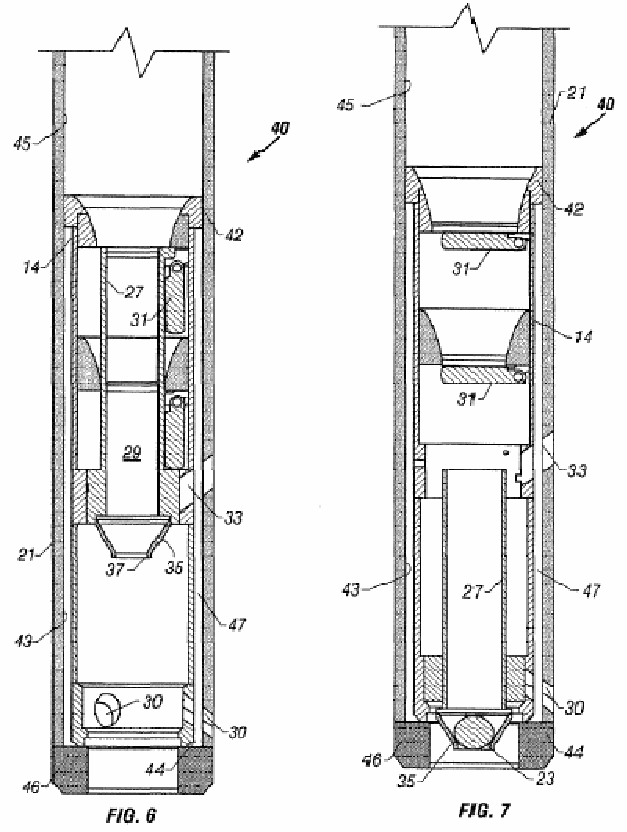
2to do so, a float equipment apparatus is connected to a tubular string—a long pipe composed of smaller sections of pipe threaded together2—and run into the wellbore. Once the apparatus has reached the desired depth, cement is pumped down the tubular string and exits below the apparatus. As the cement exits the tubular string it flows upwards toward the surface in the space between the outside of the tubular string and the sides of the wellbore, i.e. the annulus. ‘336 patent at 1:45-56. This process cements the tubular string in place, thus protecting the wellbore and allowing for deeper drilling. ‘336 patent at 2:10-16.
An embodiment of the claimed
invention is shown in the figures to the right. It consists of two flapper valves mounted to the inside of an outer tubular. The flapper valves are held in the open position by an inner tubular, as shown in figure 6. The inner tubular is held in place by a mounting member, such as one or more shear pins, shear bolts, studs, “or other breakable members.” ‘336 patent at 7:32-35. When the mounting member breaks, the inner tubular falls downward and allows
3the flapper valves to close. ‘336 patent at 7:35-45. When the flapper valves are held open by the inner tubular, the tool is in auto-fill mode— fluid may flow either toward the surface or away from the surface through the inner tubular. ‘336 patent at 4:21-25. When the flapper valves are able to close, the tool is in back pressure mode—fluid may flow downwards away from the surface, but the flapper valves prevent fluid from flowing back toward the surface. ‘336 patent at 10:59-67.
During a cementing operation, the invention is affixed to a tubular string and run down a
wellbore. A wellbore is generally filled with fluid so the tool is lowered into the wellbore while in autofill mode to allow wellbore fluid to flow upwards through the tubular string. Occasionally, the tubular string may be blocked by some obstruction in the wellbore. When this occurs, fluid is pumped down from the surface and exits through holes at or near the bottom of the tubular string, a process known as circulation. This fluid washes away the obstruction so the tubular string can be lowered further. ‘336 patent at 4:18-25. Once the tubular string reaches the desired depth, a drop member is pumped down the tubular string so that when it reaches a drop member receptacle in the inner tubular, the drop member restricts fluid flow through the inner tubular. By pumping fluid into the tubular string, fluid pressure increases and causes the mounting member to break, thus releasing the inner tubular. ‘336 patent at 8:54-9:6. Once the inner tubular is released, the flapper valves are able to close, i.e., the tool is converted to back pressure mode. Cement is now pumped down the tubular string to fill in the annulus. The flapper valves prevent the cement from flowing back into the tubular string. ‘336 patent at 1:64-2:2.
Davis-Lynch has asserted infringement of five claims in this case. Asserted independent
claim 33 covers a “float equipment assembly.” Asserted claims 34, 35, and 37 are dependent on claim 33. Asserted claim 51 is dependent on non-asserted method claim 43. The claim language is
4as follows:
33. A float equipment assembly for lowering a tubular string from a surface position
into a wellbore, said assembly comprising:
an outer tubular affixed to said tubular string; a first flapper valve body mounted within said outer tubular, said first flapper
valve body defining a first bore therethrough;
a first flapper closure element pivotally mounted to said first flapper valve body
for pivotal movement between an open position and a closed position, said first flapper closure element being selectively operable between an auto-fill mode and a back pressure mode, in said auto-fill mode said first flapper closure element being secured in said open position to permit fluid flow through said first bore in a direction toward said surface position and also to permit fluid flow in a direction away from said surface position, in said back pressure mode said first flapper closure element being pivotally moveable between said open position and said closed position responsively to fluid flow direction and being mounted to thereby prevent fluid flow through said first bore in said direction toward said surface position and to permit fluid flow in said direction away from said surface position;
a second flapper valve body mounted within said outer tubular, said second
flapper valve body defining a second bore therethrough;
a second flapper closure element pivotally mounted to said second flapper valve
body for pivotal movement between an open position and a closed position, said second flapper closure element being selectively operable between said auto-fill mode and said back pressure mode, in said auto-fill mode said second flapper closure element being secured in said open position to permit fluid flow through said second bore in said direction toward said surface position and also to permit fluid flow in said direction away from said surface position, in said back pressure mode said second flapper closure element being pivotally moveable between said open position and said closed position responsively to fluid flow direction and being mounted to thereby prevent fluid flow through said second bore in said direction toward said surface position and to permit fluid flow in said direction away from said surface position; and
an inner tubular having an inner tubular flow path therethrough, said inner tubular
being initially securable at a first axial position with respect to said outer tubular, in said first axial position said inner tubular being mounted to extend simultaneously through both said first bore and said second bore to thereby secure said first flapper closure element in said open position for operation in said auto-fill mode and to secure said second flapper closure element in said open position for operation in said auto-fill mode, said inner tubular being axially moveable from said first axial position away from said first flapper valve body and said second flapper valve body to thereby release said first flapper closure element for operation in said back pressure mode and also to
5release said second flapper element for operation in said back pressure mode.
34. The assembly of claim 33, comprising:
a drop member receptacle mounted to said inner tubular, said drop member
receptacle being operable for catching a drop member, said drop member receptacle being positioned to restrict fluid flow through said inner tubular flow path when said drop member is caught in said drop member receptacle.
35. The assembly of claim 34, further comprising:
at least one mounting member for securing said inner tubular in said first axial
position, said at least one mounting member being responsive to a first selected fluid pressure to release said inner tubular when said drop member is caught in said drop member receptacle.
37. The assembly of claim 35, further comprising:
a fluid pressure-operated tool mountable to said tubular string for operation at a
second selected fluid pressure, said second selected fluid pressure being different than said first selected fluid pressure.
43. A method for running a tubular string from a surface position into a wellbore and
for cementing said tubular string within said wellbore, said method comprising:
mounting a plurality of flapper valves, having a bore, in a float equipment tubular
attached to said tubular string;
covering said bore of said plurality of flapper valves by extending an inner tubular
through all of said plurality of flapper valves;
running said tubular string with said float equipment tubular into the wellbore
such that the wellbore fluid flows inwardly into said tubular string through said inner tubular; and
removing said inner tubular from said plurality of flapper valves such that said
flapper valves are pivotal to thereby open in response to a direction of fluid flow away from said surface position and to close in response to a direction of fluid flow towards said surface position.
51. The method of claim 43, further comprising:
providing each of said plurality of flapper valves with a bore greater than two
inches in diameter, and
providing that said tubular extending through said plurality of flapper valves has
a tubular bore with an inner diameter greater than two inches and an outer diameter less than said bore of said plurality of flapper valves.
6APPLICABLE LAW
“It is a ‘bedrock principle’ of patent law that ‘the claims of a patent define the invention to
which the patentee is entitled the right to exclude.” Phillips v. AWH Corp., 415 F.3d 1303, 1312 (Fed. Cir. 2005) (quoting Innova/Pure Water Inc. v. Safari Water Filtration Sys., Inc., 381 F.3d 1111, 1115 (Fed. Cir. 2004)). In claim construction, courts examine the patent’s intrinsic evidence to define the patented invention’s scope. See id.; C.R. Bard, Inc. v. U.S. Surgical Corp., 388 F.3d 858, 861 (Fed. Cir. 2004); Bell Atl. Network Servs., Inc. v. Covad Communications Group, Inc., 262 F.3d 1258, 1267 (Fed. Cir. 2001). This intrinsic evidence includes the claims themselves, the specification, and the prosecution history. See Phillips, 415 F.3d at 1314; C.R. Bard, Inc., 388 F.3d at 861. Courts give claim terms their ordinary and accustomed meaning as understood by one of ordinary skill in the art at the time of the invention in the context of the entire patent. Phillips, 415 F.3d at 1312-13; Alloc, Inc. v. Int’l Trade Comm’n, 342 F.3d 1361, 1368 (Fed. Cir. 2003).
The claims themselves provide substantial guidance in determining the meaning of particular
claim terms. Phillips, 415 F.3d at 1314. First, a term’s context in the asserted claim can be very instructive. Id. Other asserted or unasserted claims can also aid in determining the claim’s meaning because claim terms are typically used consistently throughout the patent. Id. Differences among the claim terms can also assist in understanding a term’s meaning. Id. For example, when a dependent claim adds a limitation to an independent claim, it is presumed that the independent claim does not include the limitation. Id. at 1314-15.
Claims “must be read in view of the specification, of which they are a part.” Id. (quoting
Markman v. Westview Instruments, Inc., 52 F.3d 967, 979 (Fed. Cir. 1995)). “[T]he specification ‘is always highly relevant to the claim construction analysis. Usually, it is dispositive; it is the single
7best guide to the meaning of a disputed term.’” Id. (quoting Vitronics Corp. v. Conceptronic, Inc., 90 F.3d 1576, 1582 (Fed. Cir. 1996)); Teleflex, Inc. v. Ficosa N. Am. Corp., 299 F.3d 1313, 1325 (Fed. Cir. 2002). This is true because a patentee may define his own terms, give a claim term a different meaning than the term would otherwise possess, or disclaim or disavow the claim scope. Phillips, 415 F.3d at 1316. In these situations, the inventor’s lexicography governs. Id. Also, the specification may resolve ambiguous claim terms “where the ordinary and accustomed meaning of the words used in the claims lack sufficient clarity to permit the scope of the claim to be ascertained from the words alone.” Teleflex, Inc., 299 F.3d at 1325. Although “it is entirely proper to use the specification to interpret what the patentee meant by a word or phrase in the claim, . . . this is not to be confused with adding an extraneous limitation appearing in the specification, which is improper. By ‘extraneous,’ we mean a limitation read into a claim from the specification wholly apart from any need to interpret . . . particular words or phrases in the claim.” E.I. du Pont de Nemours & Co. v. Phillips Petroleum Co., 849 F.2d 1430, 1433 (Fed. Cir. 1988), cert. denied, 488 U.S. 986 (1988); In re Paulsen, 30 F.3d 1475, 1480 (Fed. Cir. 1994); see also Phillips, 415 F.3d at 1323.
The prosecution history is another tool to supply the proper context for claim construction
because a patent applicant may also define a term in prosecuting the patent. Home Diagnostics, Inc., v. Lifescan, Inc., 381 F.3d 1352, 1356 (Fed. Cir. 2004) (“As in the case of the specification, a patent applicant may define a term in prosecuting a patent.”). The doctrine of prosecution disclaimer is well established and prevents a patentee from recapturing through claim interpretation specific meanings disclaimed during the prosecution of the patent. See Omega Eng'g, Inc. v. Raytek Corp., 334 F.3d 1314, 1223 (Fed.Cir.2003). The prosecution history must show that the patentee “clearly and unambiguously” disclaimed or disavowed the proposed interpretation during the patent's prosecution
8to obtain claim allowance. Middleton, Inc. v. 3M Co., 311 F.3d 1384, 1388 (Fed.Cir.2002). “Indeed, by distinguishing the claimed invention over the prior art, an applicant is indicating what the claims do not cover.” Spectrum Int'l v. Sterilite Corp., 164 F.3d 1372, 1378-79 (Fed.Cir.1998). “As a basic principle of claim interpretation, prosecution disclaimer promotes the public notice function of the intrinsic evidence and protects the public's reliance on definitive statements made during prosecution.” Omega Eng'g, Inc., 334 F.3d at 1324.
Although extrinsic evidence can be useful, it is “less significant than the intrinsic record in
determining ‘the legally operative meaning of claim language.’” Phillips, 415 F.3d at 1317 (quoting C.R. Bard, Inc., 388 F.3d at 862). Technical dictionaries and treatises may help a court understand the underlying technology and the manner in which one skilled in the art might use claim terms, but technical dictionaries and treatises may provide definitions that are too broad or may not be indicative of how the term is used in the patent. Id. at 1318. Similarly, expert testimony may aid a court in understanding the underlying technology and determining the particular meaning of a term in the pertinent field, but an expert’s conclusory, unsupported assertions as to a term’s definition is entirely unhelpful to a court. Id. Generally, extrinsic evidence is “less reliable than the patent and its prosecution history in determining how to read claim terms.” Id.
DISCUSSION
The parties dispute a number of claim terms, but many of these disputes overlap with regard
to claim scope.
I. Tubular
| Claim Term | Davis-Lynch’s Proposal | Weatherford’s Proposal |
| “outer tubular” Claims 33, 34, 35, 37 | An outer part or component shaped like a tube. | Tubular member initially located outside of and surrounding the |
| inner tubular member. | ||
| “inner tubular” Claims 33, 34, 35, 37, 51 | An inner part or component shaped like a tube. | Tubular member initially located within the outer tubular. |
| “tubular string” Claims 33, 34, 35, 37, 51 | The string of tubular components to be cemented in a wellbore or well, i.e., a casing/liner string. | Entire length of pipe run into a hole. |
| “affixed to said tubular string” Claims 33, 34, 35, 37 | Directly or indirectly attached to the tubular string. | Physically attached to the tubular string. |
9At the hearing, the parties explained that the primary dispute with regard to these terms is
whether or not the outer tubular must be a separate component from the tubular string. Davis-Lynch argues that the claimed invention does not require that the outer tubular be a separate component from the tubular string. Weatherford argues that the claimed invention is a tool, including an outer tubular, which must be separate from the tubular string.
The’336 patent almost always refers to the outer tubular as a separate component from the
tubular string. For example, it explains that the flapper valves are mounted to an outer tubular, and that this outer tubular is “cemented, molded, or otherwise mounted within a short piece of pipe.” ‘336 Patent at 7:5-6, 6:55-58. This short piece of pipe is then threaded onto the tubular string and forms a portion of the tubular string. ‘336 Patent 7:21-23; 6:58-61. The patent further explains that, unlike the tubular string, which is intended to provide permanent support to the wellbore, the outer tubular and the material for affixing the outer tubular to the tubular string may be composed of drillable material because the entire tool may later be drilled out. ‘336 patent at 7:10-24. Furthermore, every figure depicting the inner workings of the invention shows the outer tubular as
10a component separate from the tubular string.3 ‘336 patent figs. 2-9.
The patent specification contains only a single reference to support Davis-Lynch’s position.
It states that “[t]he present invention may comprise an outer tubular member forming a portion of the tubular string.” ‘336 patent at 3:41-42. In contrast to the embodiment described above, this statement appears to disclose that the flapper valves may be mounted directly to the tubular string rather than being mounted to an outer tubular affixed to the tubular string.
Although Davis-Lynch is correct to point out that the ‘336 patent discloses this alternative
embodiment, this embodiment is outside the scope of the claims asserted in this case. This embodiment appears to be covered by claims 8, 9, 10, 11, and 23, which recite “an outer tubular member forming a portion of said tubular string.” In contrast, claim 33 recites “an outer tubular affixed to said tubular string.” This statement clearly describes the “outer tubular” and “tubular string” as two separate components. Furthermore, it states that the outer tubular is “affixed” to the tubular string rather than forming a portion of it.
Davis-Lynch argues the outer tubular may be indirectly “affixed” to the tubular string if it
is glued to a section of pipe that is threaded into the tubular string, and the outer tubular may be directly “affixed” to the tubular string if the outer tubular is a section of pipe threaded directly into the tubular string. However, this interpretation finds no support in the intrinsic evidence. The word “affixed” appears twice in the patent specification. It states that the inner tubular “may be affixed in place” until it drops down during conversion. ‘336 patent at 7:28-32. It also states figure 2 depicts
11the “conversion tool” as “mounted, fastened, or affixed” to a section of pipe threaded into the tubular string. ‘336 patent at 6:55-61. In both of these statements, the word “affixed” describes the mounting of one tubular member inside another tubular member, rather than the threading together of sections of pipe. More importantly, the word “affixed” is used to describe an embodiment where the outer tubular is mounted inside the tubular string, but never used to describe an embodiment where the outer tubular forms a portion of the tubular string. ‘336 patent 6:55-61. Thus, there is no support for Davis-Lynch’s contention that the claims at issue cover an embodiment where the outer tubular forms a portion of the tubular string.
Having resolved the parties’ claim scope dispute with regard to the terms “inner tubular,”
“outer tubular,” “tubular string,” and “affixed,” the Court must now determine how best to communicate these terms to a lay jury. The Court finds that the term “affixed” is readily understandable for a jury and thus no construction is necessary. See O2 Micro Int’l Ltd. v. Beyond Innovation Tech. Co., 521 F.3d 1351, 1362 (E.D. Tex. 2008); Fenner Inv. Ltd. v. Microsoft Corp., No. 6:07-cv-8, 2008 WL 3981838 at *3 (E.D. Tex. Aug. 22, 2008) (finding that a court need not construe a disputed term as long as it has resolved the claim scope dispute between the parties). Although the Court will not construe this term, the parties may not interpret this term in a manner that is inconsistent with this opinion.
With regard to the terms “inner tubular” and “outer tubular,” the Court finds that these terms
would not be readily understood by a lay jury. The Court will not adopt Weatherford’s proposed constructions of these terms because they include a temporal component that could be confusing. Because these proposals refer to the “initial” location of the inner tubular, these proposals do not accurately describe the claimed invention when it is in back pressure mode. In contrast, Davis-
12Lynch’s proposed constructions are consistent with the patent as a whole. The one potential problem with Davis-Lynch’s proposals is that the terms “outer” and “inner” are vague. For example, because the tubular string is “outer” relative to the outer tubular, the tubular string could be described as “an outer part or component shaped like a tube.”
The difficulty in construing these terms lies in describing where these components are located
relative to one another. The patent specification overcomes this difficulty by consistently referring to the entire tool, including the inner tubular and outer tubular but not the tubular string, as “conversion tool 14” or “tool 14.” See, e.g., ‘336 patent 6:54-58, 7:4-8, 7:46-54, 9:59-61. Every figure depicting the claimed tool labels it as element 14. ‘336 patent figs. 2-9. By this consistent usage, the patentee has acted as his own lexicographer and defined the claimed tool as “tool 14.” See Phillips, 415 F.3d at 1316. Therefore, the Court will construe “inner tubular” as: “an inner part or component, of tool 14, that is shaped like a tube.” The Court will construe “outer tubular” as: “an outer part or component, of tool 14, that is shaped like a tube.”4
With regard to the term “tubular string,” the Court finds that this term would not be readily
understood by a lay jury. However, neither party has proposed an adequate construction for this term. Davis-Lynch’s proposal inappropriately equates the term “tubular string” with a “casing/liner string,” when the patent itself only lists casing and liner strings as examples of tubular strings. See, e.g., ‘336 patent at 1:14, 1:66, 5:58, 11:55. At no point does the patent expressly limit the term “tubular string” to mean simply a casing or liner string. Cf. Bell Atl. Network Servs., Inc., 262 F.3d at 1271 (“when
13a patentee uses a claim term throughout the entire patent specification, in a manner consistent with only a single meaning, he has defined that term ‘by implication’”).5 Weatherford’s proposal is flawed because it does not effectively communicate that a tubular string consists of smaller sections of pipe. Because both parties’ proposed constructions are deficient, the Court will construe “tubular string” as “a length of pipe run into a wellbore that is composed of smaller sections of pipe threaded together.”
II. Mode
| Claim Term | Davis-Lynch’s Proposal | Weatherford’s Proposal |
| “auto-fill mode” Claims 33, 34, 35, 37 | A mode of operation wherein the casing string is allowed to automatically fill by the flow of wellbore fluid toward the surface or starting position of the wellbore. | A mode of operation in which fluid may flow in either of two directions. |
| “back pressure mode” Claims 33, 34, 35, 37 | A mode of operation wherein the flapper valves are closed by and obstruct the flow of wellbore fluid toward the surface or starting position of the wellbore. | A mode of operation in which fluid flow is permitted in one direction but blocked in an opposite direction. |
As an initial matter, the Court notes that the parties have no dispute over claim scope with
regard to the term “auto-fill mode.” Both parties agree that during auto-fill mode, the flapper valves are held open to allow wellbore fluid to flow toward the surface during run in. The parties also agree that, if necessary, fluid can be pumped from the surface toward the bottom of the tubular string to clear a path for the tubular string by a process called circulation. Thus, the parties’ dispute is simply over the best way to explain this mode.
14Weatherford argues that its construction is necessary as a matter of law. It points out that the
‘336 patent is a continuation-in-part of the application that became U.S. Patent No. 6,401,824 (“the ‘824 patent”). During prosecution of the ‘336 patent, the examiner rejected claim 33 as “not patentably distinct” from claim 11 of the ‘824 patent. ‘336 patent Office Action 8/20/2008 at 8 (Doc. No. 114-6). Claim 11 is substantially similar to claim 33 of the ‘336 patent, merely substituting the terms “two-way mode” and “one way mode” for the terms “auto-fill mode” and “back pressure mode.” In order to overcome this rejection, the patentee filed a terminal disclaimer limiting the term of the ‘336 patent to coincide with the term of the ‘824 patent. Weatherford argues that because claim 11 of the ‘824 patent and claim 33 of the ‘336 patent are tied together by a terminal disclaimer, the two claims must be construed identically.
Weatherford’s argument misunderstands the purpose of a terminal disclaimer. The judicially
created doctrine of obviousness-type double patenting prevents a patentee from obtaining a patent that is an obvious variation of claims in a prior patent. See in re Vogel, 422 F.2d 438, 441-42 (C.C.P.A. 1970). The doctrine may be overcome if the applicant files a terminal disclaimer in compliance with 37 C.F.R. 1.321(b). This provision allows an applicant to “disclaim or dedicate to the public the entire term, or any terminal part of the term, of a patent to be granted.” 37 C.F.R. 1.321(b). A terminal disclaimer “‘ties the affected patents together; they expire on the same date and are enforceable only during periods in which they are owned by the same person.’” Pharmacia Corp. v. Par Pharmaceutical, Inc., 417 F.3d 1369, 1374 (Fed. Cir. 2005) (quoting DONALD S. CHISUM,
CHISUM ON PATENTS, § 9.04[5] at 9-107 (2003)).
Beyond the shared expiration date, the affected patents maintain significant attributes of
individuality. A terminal disclaimer is not an admission of obviousness and raises neither
15presumption nor estoppel as to the merits of the rejection. Quad Envtl. Tech. Corp. v. United Sanitary Dist., 946 F.2d 870, 874 (Fed. Cir. 1991). Rather, it “simply serves the statutory function of removing the rejection of double patenting.” Id. Thus, the filing of a terminal disclaimer does not require a Court to construe the claims of a terminally disclaimed patent identically with the claims of the older patent. See, e.g., Arminak & Assoc., Inc. v. Saint-Gobain Calmar, Inc., 424 F. Supp. 2d 1188, 1194 n. 1 (C.D. Cal. 2006) (“[d]espite the fact that the examiner found the two designs not patentably distinct, the Court construes the [design] patents’ claims separately to reflect differences in the two designs”); Travelers Exp. Co. v. Transaction Tracking Techs., Inc., No. 03-2848, 2005 WL 59799355 at *8 (D. Minn. May 2, 2005) (reaching the same conclusion with regard to utility patents). Thus, the Court will construe the ‘336 patent as separate from the ‘824 patent.
Having rejected Weatherford’s terminal disclaimer argument, the Court begins its analysis
by consulting the language of the claims at issue. Claim 33 explains that during auto-fill mode the flapper elements are in an “open position to permit fluid flow . . . toward said surface position and also to permit fluid flow in a direction away from said surface position.” Thus, as the parties have agreed, auto-fill mode allows for fluid flow in two directions. Nonetheless, the focus of auto-fill mode, as explained in the specification, is in allowing wellbore fluid to automatically fill up the tubular string. See ‘336 patent at 2:66-3:3, 8:1-3. The flow of fluid away from the surface is described as an optional feature of auto-fill mode. See ‘336 patent 8:17-21. While Weatherford’s proposal accurately describes “auto-fill mode,” it does so by reciting an additional limitation already mentioned in the claim language. Davis-Lynch’s proposal better reflects the meaning of the term “auto-fill mode” as used in the specification. Thus the Court will construe the term “auto-fill mode”
16as “a mode of operation wherein the tubular string (as defined herein) is allowed to automatically fill by the flow of wellbore fluid toward the surface or starting position of the wellbore.”6
A similar approach applies with regard to “back pressure mode.” Claim 33 explains that
during back pressure mode the flapper elements are in a “closed position responsively to fluid flow . . . [to] prevent fluid flow . . . toward said surface position and to permit fluid flow in said direction away from said surface position.” Thus, back pressure mode allows for fluid flow in only one direction. Nonetheless, the purpose of back pressure mode is to prevent cement pumped down the tubular string from re-entering the tubular string and flowing back toward the surface. ‘336 patent at 1:64-2:2, 2:7-10. Therefore, the Court will construe “back pressure mode” as: “A mode of operation wherein fluid flow is permitted in a direction away from the starting position of the wellbore but obstructed from flowing toward the starting position of the wellbore by flapper valves.”7
III. Simultaneously
| Claim Term | Davis-Lynch’s Proposal | Weatherford’s Proposal |
| “simultaneously” Claims 33, 34, 35, 37 | During the same time period within the same operation. | At the same time. |
| “a second flapper closure element | Davis-Lynch contends this term does not need to be defined. | A second flapper-type part or component for closing or |
| pivotally mounted to said second flapper valve body for pivotal movement between an open position and a closed position” Claims 33, 34, 35, 37 | A part or component for closing or shutting a flapper valve mounted to the second flapper valve body so as turn on, or as if on, a pivot for movement on, or as if on, a pivot between an open position and a closed position. | shutting mounted to the second flapper valve body to turn on, or as if on, a pivot to move between an open position and a closed position, wherein the second flapper closure element moves at the same time as the first flapper closure element. |
| “to thereby release said first flapper closure element . . . and also to release said second flapper closure element for operation in said back pressure mode” Claims 33, 34, 35, 37 | Davis-Lynch contends this term does not need to be defined. To thereby release the part or component for closing or shutting the flapper valve that is closest to the surface or starting position of the wellbore . . . and also to release the part of component for closing or shutting the flapper valve that is furthest away from the surface or starting position of the wellbore for operation in the mode of operation wherein the flapper valves are closed by and obstruct the flow of wellbore fluid toward the surface or starting position of the wellbore. | Releasing the first and second flapper closure elements at the same time for operation in the back pressure mode. |
| “removing said inner tubular from said plurality of flapper valves” Claim 51 | Removing the inner part or component shaped like a tube from said plurality of flapper valves. | Removing the inner tubular from the flapper valves at the same time. |
17The word “simultaneously” appears once in the ‘336 patent. Claim 33 states that the inner
tubular secures both flapper valves “simultaneously.” As explained above, the ‘336 patent teaches that both flapper valves are held open by the inner tubular during auto-fill mode, and both flapper valves are able to close during back pressure mode after the inner tubular is released.
Weatherford argues that claim 33 requires the flapper valves to open and close at the exact
same instant. It points out that, during prosecution, the patentee distinguished prior art by stating that
18the flapper valves operate “simultaneously,” and that they are converted from auto-fill mode to back pressure mode “simultaneously.” ‘336 patent Pet. to Make Special 12/13/2001 at 10 (Doc. No. 113-5). In addition, Weatherford notes that the specification states that once the inner tubular is released, the inner tubular blocks off downward angled jets and uncovers upward angled jets “at the same time.” 10:59-64. It argues that because the patentee relied on these statements to distinguish prior art, the Court must construe the claims at issue to require the flapper valves to open or close at the exact same instant.8 See Phillips, 415 F.3d at 1323 (explaining the doctrine of prosecution disclaimer).
Davis-Lynch argues that Weatherford’s proposal would exclude every disclosed embodiment
in the ‘336 patent because Weathrford’s proposal describes a situation that is not physically possible. It points out that, when the inner tubular drops, the higher flapper valve will close slightly more quickly than the lower flapper valve because it will be released sooner. Similarly, when wellbore fluid or cement is pumped down the tubular string, the higher flapper valve will open more quickly because the wellbore fluid or cement will reach it first. Furthermore, the mere fact that the patentee used the word “simultaneously” during prosecution does not support Weatherford’s proposal because that is precisely the term to be construed.
Weatherford responds that, although its proposal may render the claims impossible or
nonsensical, the Court may not redraft the claims at issue. See Process Control Corp. v. HydReclaim Corp., 190 F.3d 1350, 1357 (Fed. Cir. 1999) (“a nonsensical result does not require the court to
19redraft the claims” of a patent, where the “claims are susceptible to only one reasonable interpretation”). For example, in Chef America, Inc. v. Lamb-Weston, Inc., the patent at issue claimed a method for producing flaky, crispy dough products in a microwave. 358 F.3d 1371, 1372 (Fed. Cir. 2004). One claim step required “heating the resulting batter-coated dough to a temperature in the range of about 400oF. to 800oF.” The plaintiff argued that this step should be construed to require that the oven be heated to 400oF to 800oF because, if interpreted literally, the claim would require the dough to be burned to a crisp. Id. The Federal Circuit construed the claim literally to require that the dough be heated to 400oF to 800oF, even though this led to a nonsensical result, because the claim was susceptible to only one reasonable interpretation. Id. at 1374.
The Court agrees with Davis-Lynch, and finds the cases cited by Weatherford to be
distinguishable. Whereas the cases cited by Weatherford construed the claims at issue literally, Weatherford is attempting to import limitations not literally present in the claims. See Chef America, Inc., 358 F.3d at 1374; Process Control Corp., 190 F.3d at 1357. Furthermore, unlike the plaintiff in Chef America, Davis-Lynch has not proposed a construction that is inconsistent with the unambiguous language of the claim at issue. See Chef America, Inc., 358 F.3d at 1374. The word “simultaneously” may mean at the exact same instant, or it may mean, as Davis-Lynch correctly contends, at approximately the same time. For example, while the House and Senate may be “simultaneously” working on a bill, the two legislative bodies need not always work on their respective bills at the exact same moments. Because a person having ordinary skill in the art would understand that the inner tubular is affected by gravity and fluid pressure, that person would not expect the inner tubular to be in two places at once, or expect the flapper valves to open or close at the exact same instant. Thus, the Court rejects Weatherford’s proposed construction.
20The Court also rejects Davis-Lynch’s proposed construction because it would be confusing
for a jury. The Court will construe the term “simultaneously” as “at the same time or almost the same time,” e.g., the inner tubular holds both flapper valves open at the same time during auto-fill mode, and the flapper valves close at almost the same time during conversion and back pressure mode. This construction best captures the plain and ordinary meaning of the term “simultaneously.”
The disputes regarding the related terms above simply revolve around whether or not
Weatherford’s construction of “simultaneously” should be imported into other claim terms. See E.I. du Pont de Nemours & Co., 849 F.2d at 1433; In re Paulsen, 30 F.3d at 1480. Having rejected Weatherford’s construction, the Court will not construe these terms. See O2 Micro Int’l Ltd., 521 F.3d at 1362; Fenner Inv. Ltd., 2008 WL 3981838 at *3.
IV. Completely Sealed
| Claim Term | Davis-Lynch’s Proposal | Weatherford’s Proposal |
| “said inner tubular being mounted to extend simultaneous- ly through both said first bore and said second bore to thereby secure said first flapper closure element in said open position for operation in said auto-fill mode and to secure said second flapper closure element in said open position for operation in said auto-fill mode” Claims 33, 34, 35, 37 | Davis-Lynch contends this term does not need to be defined. The inner tubular being mounted to extend through both said first bore and said second bore during the same time period within the same operation to thereby secure the part or component for closing or shutting the flapper valve that is closest to the surface or starting position of the wellbore in the position which allows flow through for operation in the mode of operation wherein the casing string is allowed to automatically fill by the flow of wellbore fluid toward the surface or starting position of the wellbore. | The inner tubular is secured within the outer tubular to extend through the flow passageways of both the upper and lower flapper valves at the same time to completely seal off and protect the upper and lower flappers and valve seats from fluid flow. |
| “covering said bore | Davis-Lynch contends this term | Placing an inner tubular through |
| of said plurality of flapper valves by extending an inner tubular through all of said plurality of flapper valves” Claim 51 | does not need to be defined. Setting apart the flappers and valve seats of said plurality of flapper valves from the flow of wellbore fluid through the casing and preventing closure of said plurality of flapper valves. | the flow passageways of the flapper valves to completely seal off and protect the flapper valves and valve seats from fluid flow. |
21Weatherford’s proposal imports new limitations into the claims, which it argues are
mandated by the doctrine of prosecution disclaimer. See Phillips, 415 F.3d at 1323. Davis-Lynch argues that these additional limitations are extraneous. See E.I. du Pont de Nemours & Co., 849 F.2d at 1433; In re Paulsen, 30 F.3d at 1480. While Davis-Lynch agrees that the inner tubular covers and protects the flapper valves, it argues that the claims at issue do not require the flapper valves to be “completely sealed off” from fluid flow. Weatherford argues that the claims at issue must require that the flapper valves be completely sealed off from fluid flow because the patentee described that limitation as a feature of the invention as a whole, and relied on that limitation to distinguish prior art.
“When a patent thus describes the features of the ‘present invention’ as a whole, this
description limits the scope of the invention.” Verizon Servs. Corp. v. Vonage Holdings Corp., 503 F.3d 1295, 1308 (Fed. Cir. 2007). The ‘336 patent states that “the present invention teaches a means for protecting components, such as seal areas, from damage caused by the flow of cuttings or abrasive fluids.” ‘336 patent at 6:49-53. This passage indicates that protection of the flapper valves is a feature of the invention as a whole. However, the flapper valves may be protected from the flow of cuttings or abrasive fluids without being completely sealed off from wellbore fluid. See ‘336 patent at 2:58-64 (stating that the claimed invention is designed to “somehow limit damage” caused by the “flow of abrasive fluids that contain cuttings”). The ‘336 patent also states:
22“[i]n one preferred embodiment, . . . check valves 31 are completely protected from damage due to abrasive materials or cuttings that may flow through passageway 29. . . . Thus, when this embodiment of the present invention is converted to back pressure mode whereby check valves 31 are activated, then the flapper valves and their respective seats are completely free from any wear or contamination that might be caused by auto fill.”
‘336 patent at 8:25-40. This statement discloses one preferred embodiment which completely seals off and protects the flapper valves, but this embodiment is not described as the invention as a whole. Although the ‘336 patent discloses this limitation in one embodiment, the Court sees no reason to import this limitation into the claims at issue, which do not mention this limitation. See E.I. du Pont de Nemours & Co., 849 F.2d at 1433; In re Paulsen, 30 F.3d at 1480; see also Phillips, 415 F.3d at 1323.
Weatherford’s prosecution disclaimer argument is similarly overreaching. In a Petition to
Make Special,9 the patentee stated: “To avoid significant surge flow problems such as debris and erosion, Applicants also completely seal off both flapper valves as shown in FIG. 2-9 from any contamination/erosion. ‘336 patent Pet. to Make Special 12/13/2001 at 10 (Doc. No. 113-5). Weatherford argues that this statement clearly disclaims any embodiment that does not completely seal off the flapper valves. However, in the very next paragraph, the patentee states:
The advertisement of the infringing device does not actually show for sure how or even whether the flapper valves are completely protected from the debris and erosion as taught by Applicants. But clearly even the assembly configured as shown in the advertisement will be more useful and reliable for avoiding damage to the plurality of flapper valves from the surge flow erosion and debris than the prior art devices. Apparently, for that reason, the infringer has intentionally copied Applicants’ design and presently benefits greatly therefrom.
23Pet. to Make Special 12/13/2001 at 11 (Doc. No. 113-5). In this paragraph, the patentee asserts that the claimed invention includes devices that do not completely protect the flapper valves. At the very least, this paragraph renders ambiguous the statement cited by Weatherford. Accordingly, the patentee did not “clearly and unambiguously” disclaim claim scope. See Middleton, Inc., 311 F.3d at 1388.
Even if the Court accepted Weatherford’s interpretation of the patent specification and
prosecution history, the Court would not adopt Weatherford’s proposed construction. At most, the Petition to Make Special requires that the inner tubular completely seal off the flapper valves from “contamination/erosion.” ‘336 patent Pet. to Make Special 12/13/2001 at 10 (Doc. No. 113-5). Similarly, the specification would only require that the flapper valves be protected to “limit damage” from “flow of abrasive fluids that contain cuttings.” ‘336 patent at 2:58-64. Even if the Court were to import these limitations into the claims at issue, Weatherford has not shown that sealing off the flapper valves from “contamination/erosion” and limiting damage from the “flow of abrasive fluids that contain cuttings” equates to completely sealing off the flapper valves from fluid flow.10 Having rejected Weatherford’s imported limitation, the Court will not construe these terms. See O2 Micro Int’l Ltd., 521 F.3d at 1362; Fenner Inv. Ltd., 2008 WL 3981838 at *3.
24VI. Pressure
| Claim Term | Davis-Lynch’s Proposal | Weatherford’s Proposal |
| “first selected fluid pressure” Claims 35, 37 | A first fluid pressure within a predetermined or specified range. | A first chosen fluid pressure. |
| “second selected fluid pressure” Claim 37 | Fluid pressure within a predetermined or specified range different than that of a first selected fluid pressure. | A second chosen fluid pressure. |
As with a number of terms discussed above, the parties essentially agree on the claim scope
associated with these terms. The parties agree that “first selected fluid pressure” refers to the pressure at which the mounting member breaks and the tool converts, and “second selected fluid pressure” refers to the pressure at which a fluid pressure operated tool is operated. The parties agree that the exact pressure when conversion occurs or when a tool is operated cannot be predicted with absolute precision because each tool may have slight manufacturing differences and each wellbore is different. The parties agree that, at best, a manufacturer can predict a range of pressures where conversion or tool operation is most likely, but that conversion or tool operation is actually triggered at a discrete pressure. Claim 37 states that the first selected fluid pressure is different from the second selected fluid pressure. While both parties cite statements from the specification to support these agreements, neither party offers compelling evidence to support its proposal.
Davis-Lynch does not cite any evidence to support its position that these terms be construed
as referring to a range of pressures. In fact, the word “range” never appears in the patent, and the concept of pressure range is never discussed in the patent. Weatherford relies on a dictionary definition of the term “select,” to support its proposal. See WEBSTER’S THIRD NEW INT’L DICTIONARY 2058 (1986) (select: “chosen from a number or group by fitness or preference”).
25However, Weatherford’s proposal appears to indicate that an operator can choose the pressure at which conversion occurs. Weatherford admits that conversion occurs at some pressure dependent on environmental factors and the design of the mounting member, and thus its proposal is plainly inconsistent with the language of the patent. The Court finds that both parties’ proposals are inappropriate.
Because both parties’ proposals lack support, the Court will begin its analysis with the
language of the claims. Phillips, 415 F.3d at 1312; see also Network Comm, Inc. v. Microsoft Corp., 422 F.3d 1353, 1358-60 (Fed. Cir. 2005). The Court must construe a claim term as having its “ordinary and customary meaning,” that is, “the meaning that the term would have to a person of ordinary skill in the art in question at the time of the invention.” Phillips, 415 F.3d at 1313. In some cases, it is possible to construe a claim term by applying “the widely accepted meaning of commonly understood words.” Id. at 1314. These terms are not amenable to construction in this manner because they have no commonly understood meaning reflected in general dictionaries or similar sources. Nor do these terms have a “particular meaning in a field of art.” Id.
Turning to the language of the claims in which these terms appear, the Court finds that these
terms are defined in the claims themselves. Velcro Indus. B.V. v. Taiwan Paiho Ltd., No. 04-cv-242, 2005 WL 2739089 at *4 (D. N.H. Oct. 13, 2005) (quoting Interactive Gift Express, Inc v. Compuserve Inc., 256 F.3d 1323, 1331 (Fed. Cir. 2001)) (“Because the meaning of the term is clear from the language of the claim itself, the court peruses the remaining evidence for the sole purpose of ‘determining if a deviation from the clear language . . . is specified.’”). None of the evidence cited by the parties compels the Court to disregard the clear meaning of the claims. Therefore, the Court will construe “first selected fluid pressure” as “fluid pressure at which the inner tubular is released.”
26See ‘336 patent claim 35. The Court will construe “second selected fluid pressure” as “fluid pressure at which a tool is operated that is different from the first selected fluid pressure.” See ‘336 patent claim 37.
VII. Drop member
| Claim Term | Davis-Lynch’s Proposal | Weatherford’s Proposal |
| “drop member” Claims 34, 35, 37 | A ball, plug, dart, rod, shaft, or any other design for using fluid pressure. | A ball, dart, plug, or similar apparatus dropped from the surface into the wellbore. |
The ‘336 patent describes two different embodiments for releasing the inner tubular. In the
“drop embodiment,” the tool is sent to the appropriate depth in the wellbore, and then a drop member is pumped from the surface down the wellbore towards the tool. ‘336 patent 7:47-48. Fluid is continually pumped down the wellbore until the drop member reaches the drop member receptacle and restricts the flow of fluid through the inner tubular. This restriction causes fluid pressure to build up in the wellbore and break the mounting member, thus releasing the inner tubular. ‘336 patent 8:61-66. In the “cage embodiment,” the drop member is mounted to a cage-like catcher/seat above the drop member receptacle, and sent down the wellbore with the tool. Fluid pressure is used to break the cage and then push the drop member into the drop member receptacle to restrict the flow of fluid through the inner tubular. ‘336 patent 7:56-64. As with the drop embodiment, this restriction causes the inner tubular to be released. Weatherford argues that the term “drop member” refers exclusively to the drop embodiment, and that an “activation ball” is used in the cage embodiment. Davis-Lynch argues that the terms “drop member” and “activation ball” are interchangeable.
The Court must begin its analysis by consulting the claim language itself. Phillips, 415 F.3d
at 1312. The claim at issue in this case, claim 34, is broadly written to cover both the drop
27embodiment and the cage embodiment. Therefore, unless the patentee has explicitly or implicitly limited the term “drop member” to only refer to the drop embodiment, the Court will construe claim 34 to encompass both embodiments. See Aloft Media, LLC v. Microsoft Corp., No. 6:07-cv-50, 2009 WL 803133 at *3 (E.D. Tex. Mar. 24, 2009) (“Although consistent usage may define a term, particular embodiments and examples appearing in the specification should not be read into the claims.”).
Weatherford argues that the patentee implicitly limited the scope of the term “drop member”
by consistently using it to describe the drop embodiment. See Bell Atl. Network Servs., Inc., 262 F.3d at 1271 (“when a patentee uses a claim term throughout the entire patent specification, in a manner consistent with only a single meaning, he has defined that term ‘by implication’”). In every figure depicting the claimed invention, the object which lands in the drop member receptacle is labeled as element 23. Figures 2, 3, 4, and 5 contain a catcher/seat (element 23A), thus depicting the cage embodiment. See ‘336 patent 7:46-66, 8:54-66. Figures 6, 7, 8, and 9 do not contain a catcher/seat, thus depicting the drop embodiment. See ‘336 patent 9:32-58. When discussing figures 2, 3, 4, and 5, element 23 is referred to as a “ball,” “activation ball,” or “operation ball.” ‘336 patent at 7:46-47, 7:58-66, 8:62-64. When discussing figures 6, 7, 8, and 9, element 23 is referred to as a “ball,” “drop ball,” “drop element,” or “drop member.” ‘336 patent at 9:39, 9:49, 10:15-16, 10:59, 11:36-37.
This sort of consistent usage could lead one of ordinary skill in the art to conclude that the
terms “activation ball” and “drop member”refer to two different embodiments. See Bell Atl. Network Servs., Inc., 262 F.3d at 1271. However, the only term used to describe an element that employs fluid pressure to convert the inner tubular in any of the 54 claims of the ‘336 patent is “drop member.” In particular, Claims 12, 17, 18, and 54 claim “a drop member mounted adjacent to said inner
28tubular.”11 This language parallels cage embodiment language in the specification which describes an activation ball as “mounted adjacent” to the tool. ‘336 patent 7:49-51. Furthermore, Claim 18 describes using a first fluid pressure to cause the drop member to break a release member, and a second fluid pressure to cause the drop member to engage the inner tubular. Thus, claims 12, 17, 18, and 54 use the term “drop member” to describe the cage embodiment, and show that the terms “drop member” and “activation ball” must be interchangeable. See Phillips, 415 F.3d at 1314 (“Other claims of the patent in question, both asserted and unasserted, can also be valuable sources of enlightenment as to the meaning of a claim term.”).
The Court finds that the patentee has not implicitly limited the term “drop member” to refer
exclusively to the drop embodiment. Therefore, the Court will not impose a narrow restriction on the broad claim language of claim 34 as Weatherford proposes. The Court adopts Davis-Lynch’s proposed construction as consistent with the way drop member/activation ball is described in the patent. See ‘336 patent at 7:57-60.
VIII. Restrict
| Claim Term | Davis-Lynch’s Proposal | Weatherford’s Proposal |
| “being positioned to restrict fluid flow through said inner tubular flow path” Claims 34, 35, 37 | Davis-Lynch contends this term does not need to be defined. Being positioned to limit fluid flow through the path for flow through the inner tubular so as to allow for pressure build up. | Being positioned to block the flow path through the inner tubular. |
Davis-Lynch argues that this term only requires that the drop member limit fluid flow
through the inner tubular to allow pressure to build up. Weatherford maintains that the drop member
29must completely seal the flow path through the inner tubular.12 In other words, the parties dispute the meaning of the word “restrict.” This word has a “widely accepted meaning,” and nothing in the claim language compels the Court to disregard this meaning. Phillips, 415 F.3d at 1314. The commonly understood meaning of “restrict” is to limit rather than to completely seal, thus, unless the patentee has implicitly limited the scope of this term, the Court presumes that Weatherford’s proposal is inappropriate. See Brookhill-Wilk 1, LLC v. Intuitive Surgical Inc., 334 F.3d 1294, 1301 (Fed. Cir. 2003); Aloft Media, LLC, 2009 WL 803133 at *3; see also Phillips, 415 F.3d at 1312-13.
Weatherford argues that the patentee has limited the scope of this term because the
specification refers to the drop member as “sealing” the drop member receptacle to build up fluid pressure. ‘336 patent at 4:55-56, 8:60-65, 10:15-19. However, these statements in the specification do not demonstrate that the claims at issue require this limitation. The patent does not state that the invention as a whole requires the drop member to seal the drop member receptacle. Cf. Verizon Servs. Corp., 503 F.3d at 1308 (“when a patent thus describes the features of the ‘present invention’ as a whole, this description limits the scope of the invention”). At best, Weatherford has shown that the ‘336 patent discloses one embodiment in which the drop member seals the drop member receptacle. Weatherford has not shown that the limitation of this embodiment should be imported into the claims at issue. See E.I. du Pont de Nemours & Co., 849 F.2d at 1433 (explaining that Courts must not import extraneous limitations from the specification into the claims).
While Weatherford focuses on embodiments in the specification that discuss sealing the drop
member receptacle, the term to be construed is “restrict.” This word appears several times in the
30specification, and it always refers to some sort of obstruction that limits, but does not completely seal off the pathway through the tubular string. ‘336 patent 1:31-37, 6:29-36, 7:49-54, 9:51-54. Thus, the patentee has not implicitly given the term “restrict” a meaning different from its commonly understood meaning. See Bell Atl. Network Servs., Inc., 262 F.3d at 1271. Overall, Weatherford has failed to show why a limitation in one preferred embodiment should be imported into the claims at issue. Having rejected Weatherford’s argument, the Court will not construe the term at issue. See O2 Micro Int’l Ltd., 521 F.3d at 1362; Fenner Inv. Ltd., 2008 WL 3981838 at *3.
IX. Mounted to Said Inner Tubular
| Claim Term | Davis-Lynch’s Proposal | Weatherford’s Proposal |
| “mounted to said inner tubular” Claims 34, 35, 37 | Formed in, fastened, or attached to said inner tubular. | Fastened or attached to the inner tubular. |
With regard to this term, the parties dispute whether the drop member receptacle may be
“formed in” the inner tubular. To the extent that it appears elsewhere in the claims at issue, the parties have agreed to construe the term “mounted” as “fastened or attached.” (Doc. Nos. 135, 136.) This construction is consistent with the plain and ordinary meaning of the term “mounted,” and with the patent specification. For example, it describes the drop member held in a cage-like catcher/seat as being “mounted.” ‘336 patent at 7:49-51. It describes the inner tubular held in place inside the outer tubular by shear pins as being “mounted.” 7:32-35. Finally, it describes the outer tubular as being “mounted” inside the tubular string. Davis-Lynch relies on this latter example to support its construction. It points out that the patent specification states that the outer tubular may be “cemented, molded, or otherwise mounted” within the tubular string. 7:4-6. Davis-Lynch argues that the term “formed in” is synonymous with the term “molded.”
31Weatherford contends that the specification reference relied upon by Davis-Lynch is
irrelevant because it relates to the outer tubular rather than the drop member receptacle. It further contends that even if the reference were relevant, Davis-Lynch’s proposal is inconsistent with the claim language. It argues that whereas the term “mounted” relates to the fastening together of two separate objects, the term “formed in” relates to the formation of two sections of a single object. It argues that Davis-Lynch’s proposal implies that the drop member receptacle is a part of the inner tubular, rather than a separate component mounted to the inner tubular.
Weatherford correctly points out that the patent specification contains no support for Davis-
Lynch’s position that the drop member receptacle forms a part of the inner tubular. While Davis-Lynch is technically correct that the terms “formed in” and “molded” may be synonymous, the ‘336 patent never uses the term “molded” in that manner. The lone reference in the patent specification relied upon by Davis-Lynch reiterates the point that the term “molded” refers to the fastening together of two separate components. To explain how the outer tubular can be “molded, or otherwise mounted” into the tubular string, the patent specification states the outer tubular may be held in place by “cement, plastics, glues, composite materials, elastomerics, fibers or combinations of the above . . . and/or other attachment means such as braces, grips, latches, grooves, insets, threads, or the like.” ‘336 patent at 7:13-20. This passage explains that the term “molded” refers to the fastening together of two separate components, e.g., a shoe that molds to the wearer’s foot, rather than the formation of one component out of a material, e.g., molding a vase out of clay. Thus, even if the intrinsic evidence discloses that the drop member receptacle may be “molded” to the inner tubular, this provides no support for Davis-Lynch’s proposed construction of “formed in.” Weatherford’s proposed construction is consistent with every other use of the term “mounted” in the patent.
32Accordingly, the Court adopts Weatherford’s proposed construction.
X. Float equipment
| Claim Term | Davis-Lynch’s Proposal | Weatherford’s Proposal |
| “float equipment” Claim 51 | Components or parts fitted together to comprise equipment at or near the bottom of a casing string that is operable for preventing the flow of wellbore fluid through the casing toward the surface or starting position of the wellbore. | Well tool having a one-way check valve(s). |
| “float equipment tubular” Claim 51 | Components or parts fitted together to comprise equipment, shaped like a tube, at or near the bottom of a casing string that is operable for preventing the flow of wellbore fluid through the casing toward the surface or starting position of the wellbore. | Weatherford contends that the term “float equipment tubular” does not need to be defined in view of the construction of “float equipment.” A tubular for a well tool having a one-way check valve(s). |
Because the term “float equipment” does not appear separately in the claims at issue, the
Court will not construe it. Weatherford’s proposed construction of “float equipment tubular” is derived from two extrinsic sources. See A DICTIONARY OF PETROLEUM TERMS 33 (2nd ed., The University of Texas at Austin, Division of Continuing Education, Petroleum Extension Service 1979) (Drill-Pipe Float: “A valve installed in the drill stem that allows mud to be pumped down the drill stem but prevents flow back up the drill stem; a check valve”); D. LANGENKAMP, HANDBOOK OF OIL INDUSTRY TERMS & PHRASES 478 (5th ed., Penn Well Books 1994) (Valve, Check: “A valve with a free-swinging tongue or clapper that permits fluid in a pipeline to flow in one direction only; back-pressure valve”). Davis-Lynch’s proposed construction is derived from the patent specification’s definition of “float equipment”:
33As used herein, float equipment refers to equipment typically positioned near or adjacent the bottom of the tubular string such as casing or liner which contains valves that may be used to control back pressure that might permit cement to flow back into the casing/liner after cementing.
‘336 patent at 1:64-2:2. Because the patentee has explicitly defined the term “float equipment,” the Court will presume that this definition is an appropriate construction. See Phillips, 415 F.3d at 1316.
At the hearing, Davis-Lynch argued that Weatherford’s proposal was overly broad because
it did not explain that fluid is only blocked from flowing toward the surface. However, the patentee’s definition of “float equipment” merely states that the valves “may be used to control back pressure that might permit cement to flow back into the casing/liner after cementing.” ‘336 patent at 1:64-2:2 (emphasis added). Thus, Davis-Lynch’s argument imposes a limitation not present in the patentee’s explicit definition of the term float equipment. Weatherford argued, at the hearing, that Davis-Lynch’s proposal impermissibly imports its proposed construction of tubular string and adds the limitation that the equipment must be located at the bottom of the tubular string. Weatherford’s arguments are well taken. Having rejected Davis-Lynch’s construction of the term “tubular string,” the Court sees no reason to replace the phrase “tubular string” with the phrase “casing string.” Similarly, the Court sees no reason to import the limitation that float equipment must be located at the bottom of a tubular string, when the patentee’s definition states only that float equipment is “typically” located there. The use of the word “typically” implies that float equipment need not always be located at the bottom of a tubular string. See ‘336 patent at 1:65-66.
The Court finds the patentee’s own definition of the term at issue to be understandable for
a jury. However, the terms casing and liner could be confusing since the claims at issue only refer to tubular strings. In addition, the phrase “may be used to control back pressure . . .” must be
34removed because it merely describes a possible use for the flapper valves. Therefore, the Court will construe the term “float equipment tubular” as “tube-shaped equipment typically positioned near or adjacent to the bottom of the tubular string (as defined herein), which contains valves.”
XI. Preamble Terms
The preamble to claim 33 states: “A Float equipment assembly for lowering a tubular string
from a surface position into a wellbore.” The preamble to claim 43 states: “A method for running a tubular string from a surface position into a wellbore and for cementing said tubular string within said wellbore.” Davis-Lynch argues that these preambles contains limitations that apply to the claims at issue. Weatherford argues that the preambles are non-limiting because they merely describe intended uses of the claimed inventions.
A. Applicable Law
A patent claim typically contains three parts: the preamble, the transition, and the body.
DONALD S. CHISUM, CHISUM ON PATENTS § 806[1](b) (2003). “The preamble is an introductory phrase that may summarize the invention, its relation to the prior art, or its intended use or properties.” Id. A claim preamble may be regarded as a “claim element” and therefore limiting only “if it recites essential structure or steps, or if it is necessary to give ‘life, meaning, and vitality’ to the claim.” Intirtool, Ltd. v. Texar Corp., 369 F.3d 1289, 1295 (Fed. Cir. 2004) (quotation marks omitted) (quoting Pitney Bowes, Inc. v. Hewlett-Packard Co., 182 F.3d 1298, 1305 (Fed. Cir. 1999)). However, the preamble is generally not limiting if the body of the claim “describes a structurally complete invention such that deletion of the preamble phrase does not affect the structure or steps
35of the claimed invention.” Id. (quotation marks omitted) (quoting Catalina Mktg. Int’l, Inc. v. Coolsavings.com, Inc., 289 F.3d 801, 808-09 (Fed. Cir. 2002)). Thus:
[Where] the body of the claim fully and intrinsically sets forth the complete invention, including all of its limitations, and the preamble offers no distinct definition of any of the claimed invention’s limitations, but rather merely states, for example, the purpose or intended use of the invention, then the preamble is of no significance to claim construction because it cannot be said to constitute or explain a claim limitation.
Pitney Bowes, 182 F.3d at 1305.
In Pitney Bowes, Inc. v. Hewlett-Packard Co. the Federal Circuit found limiting the
preamble: “A method of producing on a photoreceptor an image of generated shapes made up of spots.” Id. at 1306. The Court determined that the terms “generated shapes” and “spots,” as used in two independent claims, could not be understood without the preamble as context. Similarly, in Bell Communications Research, Inc. v. Vitalink Communications Corp. the Federal Circuit found limiting the preamble: “A method for transmitting a packet over a system comprising a plurality of networks interconnected by gateways, . . . said packet including a source address and a destination address.” 55 F.3d 615, 618 (Fed. Cir. 1995). The Court concluded that the preamble’s requirement that a packet include a source address and a destination address is a limitation, even though it is not repeated in the body of the claim. See id. at 621.
In contrast, in Intirtool, Ltd. v. Texar Corp., the Federal Circuit found not limiting the
preamble: “A hand-held punch pliers for simultaneously punching and connecting overlapping sheet metal such as at the corners of overlapping ceiling tile grids.” 369 F.3d at 1292. The Court found that the phrase “for simultaneously punching and connecting” merely recited a benefit or feature of the invention, not a limitation. Id. at 1296. In Vaupel Textilmaschinen KG v. Meccanica Euro Italia SPA,
36the Federal Circuit found not limiting the preamble: “A method of forming a plurality of patterned strips of fabric woven from threads of synthetic material using a broad weaving machine having a sley and a breast beam.” 944 F.2d 870, 872 (Fed. Cir. 1991). The Court concluded that the claim did not require a “breast beam” because this term was used only to indicate a reference point to fix the direction of movement of the woven fabric from the loom. Id. at 880. The Court noted that neither the specification nor any of the figures indicated that a “breast beam” is a structural limitation.
B. Preamble Terms at Issue
| Claim Term | Davis-Lynch’s Proposal | Weatherford’s Proposal |
| “ f l o a t e q u i p m e n t assembly” Claims 33, 34, 35, 37 | Components or parts fitted together to comprise equipment at or near the bottom of a casing string that is operable for preventing the flow of wellbore fluid through the casing toward the surface or starting position of the wellbore. | Preamble not limiting. |
| “lowering a tubular string from a surface position into a wellbore” Claims 33, 34, 35, 37 | Inserting a tubular string into a wellbore from the surface or starting position of the wellbore. | Preamble not limiting. |
| “running a tubular string from a surface position into a wellbore” Claim 51 | Inserting into a wellbore from the surface or starting position of the wellbore. | Preamble not limiting. |
| “cementing said tubular string with in said wellbore” Claim 51 | Filling the annulus between the casing and the wall of the wellbore with cement to support the casing and prevent fluid migration between zones. | Preamble not limiting. |
As explained above in section X, the patentee has given a particular meaning to the term “float
equipment.” This meaning, as construed by the Court, is: “equipment typically positioned near or adjacent to the bottom of the tubular string which contains valves.” Although the bodies of the claims
37at issue do not state the tool is typically located at the bottom of a tubular string, this feature is consistently referred to in the patent specification. For example, the patent frequently refers to the claimed invention as a float shoe/collar, which Weatherford agrees must be located at the bottom of a tubular string. See, e.g., ‘336 patent at 2:66-3:1, 9:32-33, 10:19-21, 10:50-51. Accordingly, the term “float equipment assembly,” as defined by the patentee and construed by the Court, gives “life, meaning, and vitality” to the claims. See Intirtool, Ltd. v. Texar Corp., 369 F.3d at 1295; see, e.g., Bell Commc’ns Research, Inc., 55 F.3d at 618. The Court will construe the term “float equipment assembly” consistently with the term “float equipment tubular” as: “equipment typically positioned near or adjacent to the bottom of the tubular string (as defined herein), which contains valves.”
The remaining preamble terms merely state the “purpose or intended use” of the invention.
See Pitney Bowes, 182 F.3d at 1305; Intirtool, Ltd., 369 F.3d at 1296. These terms directly parallel the preamble term found to be non-limiting in Intirtool. They simply state that the invention is “for lowering a tubular string,” “for running a tubular string,” and “for cementing said tubular string.” See id. Because deletion of these preamble terms does not affect the structure or steps of the claimed invention, these terms do not limit the claims. Id. at 1295.
XII. Agreed Terms
Prior to the hearing, the parties agreed to the construction of a number of terms. These
constructions have been set forth as Appendix B. At the hearing the parties agreed: the term “bore” will not be construed; and the term “flapper closure element” will not be construed. After the hearing the parties agreed: the term “mounted within the outer tubular” will be construed as “fastened or attached within the outer tubular;” the term “mountable to said tubular string” will be construed as “capable of being fastened or attached to the tubular string;” the term “mounting member for
38securing” will be construed as “item for securing.” (Doc. No. 139.)
CONCLUSION
For the foregoing reasons, the Court interprets the claim language in this case in the manner .
set forth above. For ease of reference, the Court's claim interpretations are set forth in tables attached to this opinion as Appendices A and B.
So ORDERED and SIGNED this 20th day of April, 2009.
JOHN D. LOVE
UNITED STATES MAGISTRATE JUDGE
39APPENDIX A – THE COURT’S CONSTRUCTIONS
| No. | Claim Term | Davis-Lynch’s Proposal | Weatherford’s Proposal | Court’s Construction |
| D1 | “outer tubular” Claims 33, 34, 35, 37 | An outer part or component shaped like a tube. | Tubular member initially located outside of and surrounding the inner tubular member. | An outer part or component, of tool 14, that is shaped like a tube |
| D2 | “inner tubular” Claims 33, 34, 35, 37, 51 | An inner part or component shaped like a tube. | Tubular member initially located within the outer tubular. | An inner part or component, of tool 14, that is shaped like a tube |
| D3 | “tubular string” Claims 33, 34, 35, 37, 51 | The string of tubular components to be cemented in a wellbore or well, i.e., a casing/liner string. | Entire length of pipe run into a hole. | A length of pipe run into a wellbore that is composed of smaller sections of pipe threaded together |
| D4 | “simultaneous” Claims 33, 34, 35, 37 | During the same time period within the same operation. | At the same time. | At the same time or almost the same time |
| D5 | “auto-fill mode” Claims 33, 34, 35, 37 | A mode of operation wherein the casing string is allowed to automatically fill by the flow of wellbore fluid toward the surface or starting position of the wellbore. | A mode of operation in which fluid may flow in either of two directions. | A mode of operation wherein the tubular string (as defined herein) is allowed to automatically fill by the flow of wellbore fluid toward the surface or starting position of the wellbore. |
| D6 | “back pressure mode” Claims 33, 34, 35, 37 | A mode of operation wherein the flapper valves are closed by and obstruct the flow of wellbore fluid toward the surface or starting position | A mode of operation in which fluid flow is permitted in one direction but blocked in an opposite direction. | A mode of operation wherein fluid flow is permitted in a direction away from the starting position of the wellbore but |
39
| No. | Claim Term | Davis-Lynch’s Proposal | Weatherford’s Proposal | Court’s Construction |
| of the wellbore. | obstructed from flowing toward the starting position of the wellbore by flapper valves. | |||
| D7 | “first selected fluid pressure” Claims 35, 37 | A first fluid pressure within a predetermined or specified range. | A first chosen fluid pressure. | Fluid pressure at which the inner tubular is released |
| D8 | “second selected fluid pressure” Claim 37 | Fluid pressure within a predetermined or specified range different than that of a first selected fluid pressure. | A second chosen fluid pressure. | Fluid pressure at which a tool is operated that is different from the first selected fluid pressure |
| D9 | “affixed to said tubular string” Claims 33, 34, 35, 37 | Directly or indirectly attached to the tubular string. | Physically attached to the tubular string. | No construction necessary |
| D10 | “float equipment” Claim 51 | Components or parts fitted together to comprise equipment at or near the bottom of a casing string that is operable for preventing the flow of wellbore fluid through the casing toward the surface or starting position of the wellbore. | Well tool having a one-way check valve(s). | No construction necessary |
| D11 | “float equipment tubular” Claim 51 | Components or parts fitted together to comprise equipment, shaped like a tube, at or near the bottom of a casing string | Weatherford contends that the term “float equipment tubular” does not need to be defined in view of the | Tube-shaped equipment typically positioned near or adjacent to the bottom of the |
4040
| No. | Claim Term | Davis-Lynch’s Proposal | Weatherford’s Proposal | Court’s Construction |
| that is operable for preventing the flow of wellbore fluid through the casing toward the surface or starting position of the wellbore. | construction of “float equipment.” A tubular for a well tool having a one- way check valve(s). | tubular string (as defined herein), which contains valves | ||
| D12 | “mountable to said tubular string” Claim 37 | [AGREED] | [AGREED] | Capable of being fastened or attached to the tubular string |
| D13 | “mounted within said outer tubular” Claims 33, 34, 35, 37 | [AGREED] | [AGREED] | Fastened or attached within the outer tubular |
| D14 | “mounted to said inner tubular” Claims 34, 35, 37 | Formed in, fastened, or attached to said inner tubular. | Fastened or attached to the inner tubular. | Fastened or attached to the inner tubular |
| D15 | “bore” Claims 33, 34, 35, 37 | [AGREED] | [AGREED] | No construction necessary |
| D16 | “flapper closure element” Claims 33, 34, 35, 37 | [AGREED] | [AGREED] | No construction necessary |
| D17 | “removing said inner | Removing the inner part or component | Removing the inner tubular from the | No construction necessary |
4141
| No. | Claim Term | Davis-Lynch’s Proposal | Weatherford’s Proposal | Court’s Construction |
| tubular from said plurality of flapper valves” Claim 51 | shaped like a tube from said plurality of flapper valves. | flapper valves at the same time. | ||
| D18 | “drop member” Claims 34, 35, 37 | A ball, plug, dart, rod, shaft, or any other design for using fluid pressure. | A ball, dart, plug, or similar apparatus dropped from the surface into the wellbore. | A ball, plug, dart, rod, shaft, or any other design for using fluid pressure. |
| D19 | “mounting member for securing” Claims 35, 37 | [AGREED] | [AGREED] | Item for securing |
| D20 | “being positioned to restrict fluid flow through said inner tubular flow path” Claims 34, 35, 37 | Davis-Lynch contends this term does not need to be defined. Being positioned to limit fluid flow through the path for flow through the inner tubular so as to allow for pressure build up. | Being positioned to block the flow path through the inner tubular. | No construction necessary |
| D21 | “covering said bore of said plurality of flapper valves by extending an inner tubular through all of said plurality of flapper valves” Claim 51 | Davis-Lynch contends this term does not need to be defined. Setting apart the flappers and valve seats of said plurality of flapper valves from the flow of wellbore fluid through the casing and preventing closure of said plurality of flapper valves. | Placing an inner tubular through the flow passageways of the flapper valves to completely seal off and protect the flapper valves and valve seats from fluid flow. | No construction necessary |
4242
| No. | Claim Term | Davis-Lynch’s Proposal | Weatherford’s Proposal | Court’s Construction |
| D22 | “a second flapper closure element pivotally mounted to said second flapper valve body for pivotal movement between an open position and a closed position” Claims 33, 34, 35, 37 | Davis-Lynch contends this term does not need to be defined. A part or component for closing or shutting a flapper valve mounted to the second flapper valve body so as turn on, or as if on, a pivot for movement on, or as if on, a pivot between an open position and a closed position. | A second flapper-type part or component for closing or shutting mounted to the second flapper valve body to turn on, or as if on, a pivot to move between an open position and a closed position, wherein the second flapper closure element moves at the same time as the first flapper closure element. | No construction necessary |
| D23 | “said inner tubular being mounted to extend simultaneously through both said first bore and said second bore to thereby secure said first flapper closure element in said open position for operation in said auto-fill mode and to secure said second flapper closure element in said open position for operation in said auto-fill mode” Claims 33, 34, 35, 37 | Davis-Lynch contends this term does not need to be defined. The inner tubular being mounted to extend through both said first bore and said second bore during the same time period within the same operation to thereby secure the part or component for closing or shutting the flapper valve that is closest to the surface or starting position of the wellbore in the position which allows flow through for operation in the mode of operation wherein the casing string is allowed to automatically fill by the flow of wellbore fluid toward the surface or starting position of the wellbore. | The inner tubular is secured within the outer tubular to extend through the flow passageways of both the upper and lower flapper valves at the same time to completely seal off and protect the upper and lower flappers and valve seats from fluid flow. | No construction necessary |
4343
| No. | Claim Term | Davis-Lynch’s Proposal | Weatherford’s Proposal | Court’s Construction |
| D24 | “to thereby release said first flapper closure element…and also to release said second flapper closure element for operation in said back pressure mode” Claims 33, 34, 35, 37 | Davis-Lynch contends this term does not need to be defined. To thereby release the part or component for closing or shutting the flapper valve that is closest to the surface or starting position of the wellbore … and also to release the part of component for closing or shutting the flapper valve that is furthest away from the surface or starting position of the wellbore for operation in the mode of operation wherein the flapper valves are closed by and obstruct the flow of wellbore fluid toward the surface or starting position of the wellbore. | Releasing the first and second flapper closure elements at the same time for operation in the back pressure mode. | No construction necessary |
| D25 | “float equipment assembly” Preamble to Claims 33, 34, 35, 37 | Components or parts fitted together to comprise equipment at or near the bottom of a casing string that is operable for preventing the flow of wellbore fluid through the casing toward the surface or starting position of the wellbore. | Preamble not limiting. | Equipment typically positioned near or adjacent to the bottom of the tubular string (as defined herein), which contains valves |
| D26 | “lowering a tubular string from a surface position into a wellbore” Preamble to Claims 33, 34, 35, 37 | Inserting a tubular string into a wellbore from the surface or starting position of the wellbore. | Preamble not limiting. | Preamble not limiting. |
4444
| No. | Claim Term | Davis-Lynch’s Proposal | Weatherford’s Proposal | Court’s Construction |
| D27 | “running a tubular string from a surface position into a wellbore” Preamble to Claim 51 | Inserting into a wellbore from the surface or starting position of the wellbore. | Preamble not limiting. | Preamble not limiting. |
| D28 | “cementing said tubular string within said wellbore” Preamble to Claim 51 | Filling the annulus between the casing and the wall of the wellbore with cement to support the casing and prevent fluid migration between zones. | Preamble not limiting. | Preamble not limiting. |
4545
46APPENDIX B – THE PARTIES’ AGREED CONSTRUCTIONS
| No. | Claim Term | Davis-Lynch’s Proposal | Weatherford’s Proposal | Court’s Construction |
| A1 | “pivotal” Claims 33, 34, 35, 37, 51 | [AGREED] | [AGREED] | Able to move on, or as if on, a pivot. |
| A2 | “flapper valve body” Claims 33, 34, 35, 37 | [AGREED] | [AGREED] | The main or central part of a flapper valve. |
| A3 | “defining” Claims 33, 34, 35, 37 | [AGREED] | [AGREED] | Determining or setting the boundaries of. |
| A4 | “closure element” Claims 33, 34, 35, 37 | [AGREED] | [AGREED] | Part or component for closing or shutting. |
| A5 | “pivotally mounted” Claims 33, 34, 35, 37 | [AGREED] | [AGREED] | Mounted to turn on, or as if on, a pivot. |
| A6 | “pivotally mounted to said first flapper valve body” Claims 33, 34, 35, 37 | [AGREED] | [AGREED] | Mounted to the main or central part of a first flapper valve so as to turn on, or as if on, a pivot. |
| A7 | “pivotally mounted to said second flapper valve body” | [AGREED] | [AGREED] | Mounted to the main or central part of a second flapper valve so |
46
| No. | Claim Term | Davis-Lynch’s Proposal | Weatherford’s Proposal | Court’s Construction |
| Claims 33, 34, 35, 37 | as to turn on, or as if on, a pivot. | |||
| A8 | “pivotal movement” Claims 33, 34, 35, 37 | [AGREED] | [AGREED] | Movement on, or as if on, a pivot. |
| A9 | “for pivotal movement” Claims 33, 34, 35, 37 | [AGREED] | [AGREED] | For movement on, or as if on, a pivot. |
| A10 | “being selectively operable between an auto-fill mode and a back pressure mode” Claims 33, 34, 35, 37 | [AGREED] | [AGREED] | Capable of being operated in an auto-fill mode and a back pressure mode. |
| A11 | “secured in said open position” Claims 33, 34, 35, 37 | [AGREED] | [AGREED] | Held in the open position. |
| A12 | “pivotally moveable” Claims 33, 34, 35, 37 | [AGREED] | [AGREED] | Movable on, or as if on, a pivot. |
| A13 | “responsively to fluid flow direction” | [AGREED] | [AGREED] | In response to the direction of fluid flow. |
4747
| No. | Claim Term | Davis-Lynch’s Proposal | Weatherford’s Proposal | Court’s Construction |
| Claims 33, 34, 35, 37 | ||||
| A14 | “being mounted to thereby prevent fluid flow through said first bore in said direction toward said surface position and to permit fluid flow in said direction away from said surface position” Claims 33, 34, 35, 37 | [AGREED] | [AGREED] | Being mounted to thereby block the flow of fluid through the first bore in a direction toward the surface or starting position of the wellbore and to allow the flow of fluid in a direction away from the surface or starting position of the wellbore. |
| A15 | “being mounted to thereby prevent fluid flow through said second bore in said direction toward said surface position and to permit fluid flow in said direction away from said surface position” Claims 33, 34, 35, 37 | [AGREED] | [AGREED] | Being mounted to thereby block the flow of fluid through the second bore in a direction toward the surface or starting position of the wellbore and to allow the flow of fluid in a direction away from the surface or starting position of the wellbore. |
| A16 | “inner tubular flow path” Claims 33, 34, 35, 37 | [AGREED] | [AGREED] | A path for flow through the inner tubular. |
| A17 | “initially securable” | [AGREED] | [AGREED] | Able to be initially held. |
4848
| No. | Claim Term | Davis-Lynch’s Proposal | Weatherford’s Proposal | Court’s Construction |
| Claims 33, 34, 35, 37 | ||||
| A18 | “first axial position with respect to said outer tubular” Claims 33, 34, 35, 37 | [AGREED] | [AGREED] | The first location at which the inner tubular is secured with respect to the outer tubular. |
| A19 | “axially moveable” Claims 33, 34, 35, 37 | [AGREED] | [AGREED] | Movable on or along an axis. |
| A20 | “drop member receptacle” Claims 34, 35, 37 | [AGREED] | [AGREED] | Part or surface for catching or holding a drop member. |
| A21 | “operable for catching a drop member” Claims 34, 35, 37 | [AGREED] | [AGREED] | Capable of catching a drop member. |
| A22 | “a fluid pressure-operated tool” Claim 37 | [AGREED] | [AGREED] | A tool operated with fluid pressure. |
| A23 | “mounting a plurality of flapper valves” | [AGREED] | [AGREED] | Mounting more than one flapper valve. |
4949
| No. | Claim Term | Davis-Lynch’s Proposal | Weatherford’s Proposal | Court’s Construction |
| Claim 51 | ||||
| A24 | “running” Claim 51 | [AGREED] | [AGREED] | Lowering or inserting. |
| A25 | “wellbore fluid” Claim 51 | [AGREED] | [AGREED] | Fluid naturally present and/or placed in a wellbore. |
| A26 | “selectively operable” Claims 33, 34, 35, 37 | [AGREED] | ]AGREED] | [plain language meaning; no need for construction] |
| A27 | “open position” Claims 33, 34, 35, 37 | [AGREED] | [AGREED] | [plain language meaning; no need for construction] |
| A28 | “closed position” Claims 33, 34, 35, 37 | [AGREED] | [AGREED] | [plain language meaning; no need for construction] |
| A29 | “being responsive to a first selected fluid pressure” Claims 35, 37 | [AGREED] | [AGREED] | [to be determined by plain language meaning and construction of disputed term “first selected fluid pressure”; no need for separate construction] |
5050
| No. | Claim Term | Davis-Lynch’s Proposal | Weatherford’s Proposal | Court’s Construction |
| A30 | “for operation at a second selected fluid pressure” Claim 37 | [AGREED] | [AGREED] | [to be determined by plain language meaning and construction of disputed term “second selected fluid pressure”; no need for separate construction] |
| A31 | “wellbore” Claim 51 | [AGREED] | [AGREED] | [plain language meaning; no need for construction] |
5151
Footnotes
- ↩ 1 At the hearing, the Court encouraged the parties to agree to constructions of several terms, and instructed the parties to file a notice with the Court detailing any agreements the parties had reached. Instead, Davis-Lynch unilaterally filed a Notice Regarding Claim Construction Compromise Proposals in which it offered new proposed constructions for several terms, and apparently agreed to three constructions proposed by the Court at the hearing. (Doc. No. 135.) Weatherford filed Responses in which it reiterated its agreement with the three constructions proposed by the Court at the hearing, and explained its disagreement with Weatherford’s new proposals. (Doc. Nos. 136, 140.) Davis-Lynch later filed a Joint Notice which explained that the parties had agreed to constructions of three terms. (Doc. No. 139.) Although the Court has considered Davis-Lynch’s compromise proposals, these filings are symptomatic of the lack of communication and petty disagreements that have characterized this case. The Court encourages counsel for both parties to communicate more openly.
- ↩ 2 That is, connected by spiral ridges, e.g., nuts and bolts.
- ↩ 3 The outer tubular is labeled as element 25 in figures 2-5, but it is not separately labeled in figures 6-9. Nonetheless, figures 6-9 clearly show that the flapper valves are attached to a component separate from the tubular string. This component must be the outer tubular. Furthermore, figures 6 and 7 show that “conversion tool 14 [i.e. the entire tool including the outer tubular,] is mounted within pipe 21 [i.e. the tubular string].” ‘336 patent at 9:59-60. Figures 8 and 9 show that “conversion tool 14 may be mounted by any suitable means within collar section 21A [i.e. the tubular string].” ‘336 patent at 10:29-30.
- ↩ 4 While the Court recognizes that claim terms are typically not construed by reference to elements in the patent’s figures, such references may be appropriate when they best explain the term in dispute. See, e.g., Rapistan Sys. Advertising Corp. v. Daifuku America Corp., No. 03-CA-682, 2006 WL 6112186 at *12 (W.D. Tex. Feb. 9, 2006) (construing the term “joining edges” by reference to a figure in the patent because the parties’ proposed constructions did not adequately explain the term).
- ↩ 5 The Court also finds that Davis-Lynch’s proposal unnecessarily describes the tubular string as being “cemented into the wellbore.” This issue is addressed more fully below in section X.
- ↩ 6 This construction is essentially the same as Davis-Lynch’s construction except that the phrase “casing string” has been replaced with the phrase “tubular string” to be consistent with the actual language of the claims at issue.
- ↩ 7 Davis-Lynch offered this proposed construction as a compromise proposal after the hearing. (Doc. No. 135.) Davis-Lynch’s original proposal was: “a mode of operation wherein the flapper valves are closed by and obstruct the flow of wellbore fluid toward the surface or starting position of the wellbore.” At the hearing, Weatherford argued that this original proposal was inappropriate because it stated that “the flapper valves are closed by . . . the flow of wellbore fluid.” Weatherford argued that the ‘336 patent only discloses closing the flapper valves by some sort of spring bias, not by the flow of wellbore fluid. Because the construction adopted by the Court does not state that the flapper valves are closed by fluid flow, the Court will not address Weatherford’s argument.
- ↩ 8 At the hearing, Weatherford presented the Court with diagrams of other devices which Weatherford claimed were distinguished during prosecution by arguing that the flapper valves close at the exact same instant. Weatherford included at least one of these diagrams as exhibit T to its claim construction brief, but it never cited or explained the exhibit in its brief. Regardless, Weatherford has not cited any statement to support its claim that, during prosecution, Davis-Lynch argued that the flapper valves close at the exact same instant.
- ↩ 9 A Petition to Make Special allows an applicant to request that the PTO advance an application for examination out of turn. 37 C.F.R. 1.102. In this case, the patentee’s basis for seeking advancement was that an infringing product was already on the market.
- ↩ 10 Weatherford argues that the flow of water may cause erosion over time. Therefore, Weatherford argues that in order to seal the flapper valves off from “contamination/erosion,” the flapper valves must be completely sealed off from wellbore fluid. While Weatherford is technically correct that water can cause erosion, the patent does not use the term “erosion” so broadly. Rather, the references cited above explain that the flapper valves must be protected from abrasive fluids and cuttings. This may be accomplished even if small amounts of wellbore fluid come into contact with the flapper valves.
- ↩ 11 Claim 12 recites “a drop member mounted adjacent to said moveable member.”
- ↩ 12 Although Weatherford proposes that the term “restrict” be construed as “block,” Weatherford’s brief makes clear that it believes this term requires the drop member to “completely seal” the drop member receptacle.